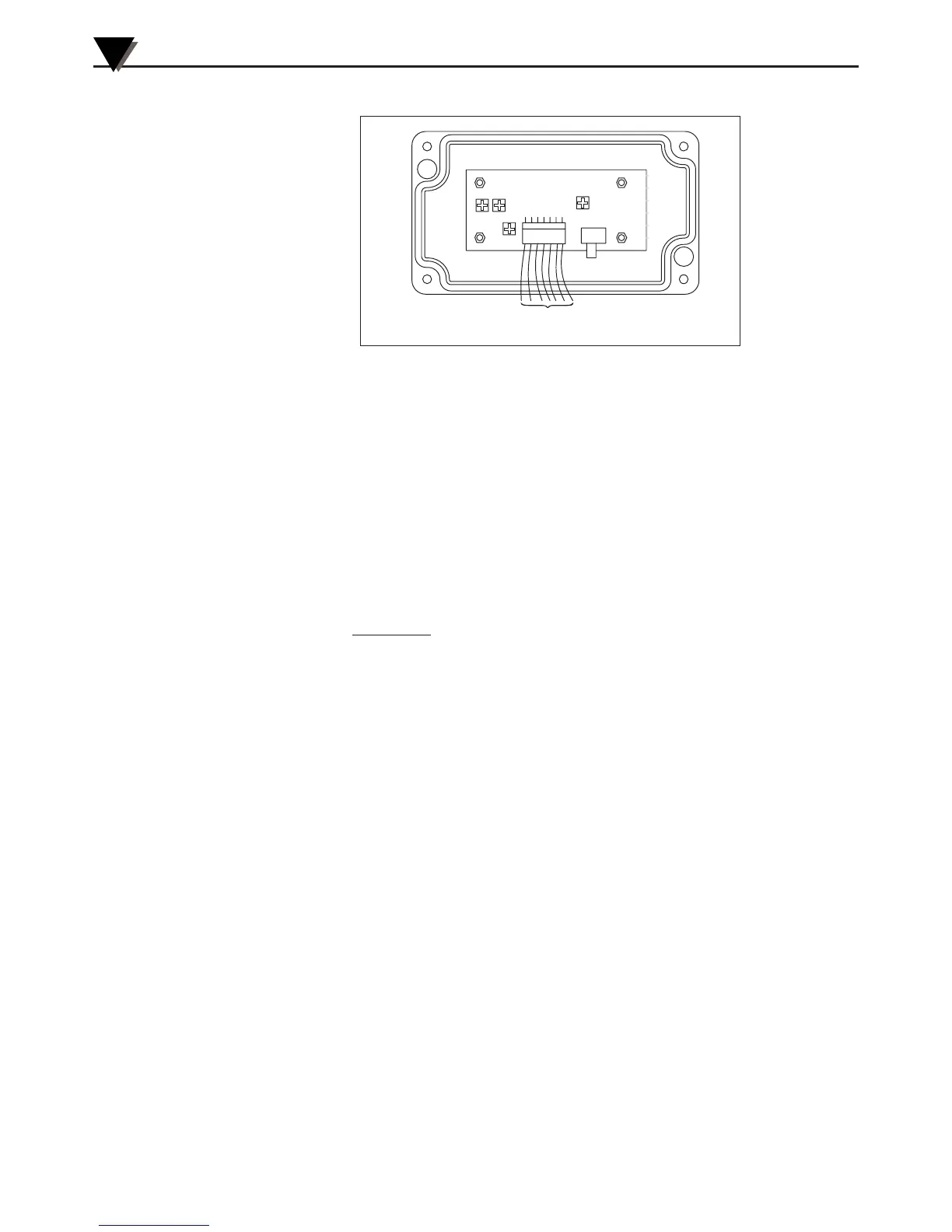
Figure 3-4. Setting the Temperature Engineering Unit
3.5 Alarm Setting
The unit provides 0-100% alarm set point adjustment. Here is an example
of an alarm setting.
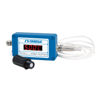
• An OS101-MA (4/20 mA output), the alarm is to be set at 400°F
temperature.
• Connect the alarm output as shown in Fig. 2-2.
• Set the slide switch (SW1) on the main board to the Alarm position.
• Measure the analog output, and set the Potentiometer P4 until the
output reads 10.4 mA which is 40% (400°F) of the temperature range.
40 x (20-4)
[10.4mA =
100
+ 4]
• Set the slide switch (SW1) back to the Real Time position.
• If the temperature reading is below the alarm set point, the alarm
output stays high, otherwise it goes low.
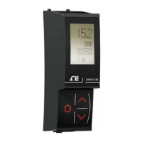
On the OS102, you can set the alarm set point directly based on the
temperature display.
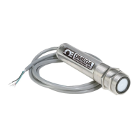
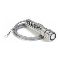
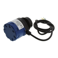
3.6 Adding Extension Cable
You can add extension cable between the Sensor Head and the main
electronic housing up to 15.2 m (50 feet). After adding the extension cable,
the Zero input potentiometer, P3 may be re-adjusted. (See Fig. 3-1, for
proper analog output reading)
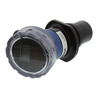
The following figures show the mounting bracket (OS100-MB), Water
cooling jacket (OS100-WC), Air purge collar (OS100-AP), DIN Rail
Mounting adapter (OS-100-DR), and the main aluminum enclosure. The
DIN Rail Mounting adapter (OS100-DR) is mounted to the bottom of the
main aluminum enclosure using two 4-40 screws.
A typical water cool jacket assembly is shown in Fig. 3-7, on the following page.
1. Mounting Nut
2. Mounting Bracket
3. Water Cool Jacket
4. Sensor Head
OS100 Series - Operation
3
3-4
 Loading...