GPS Synchronization Unit CMGPS
26
4.1 Connecting the CMGPS to a CMC Test Set
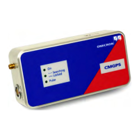
Figure 4-1:
CMGPS communication
interface ext. Interf.
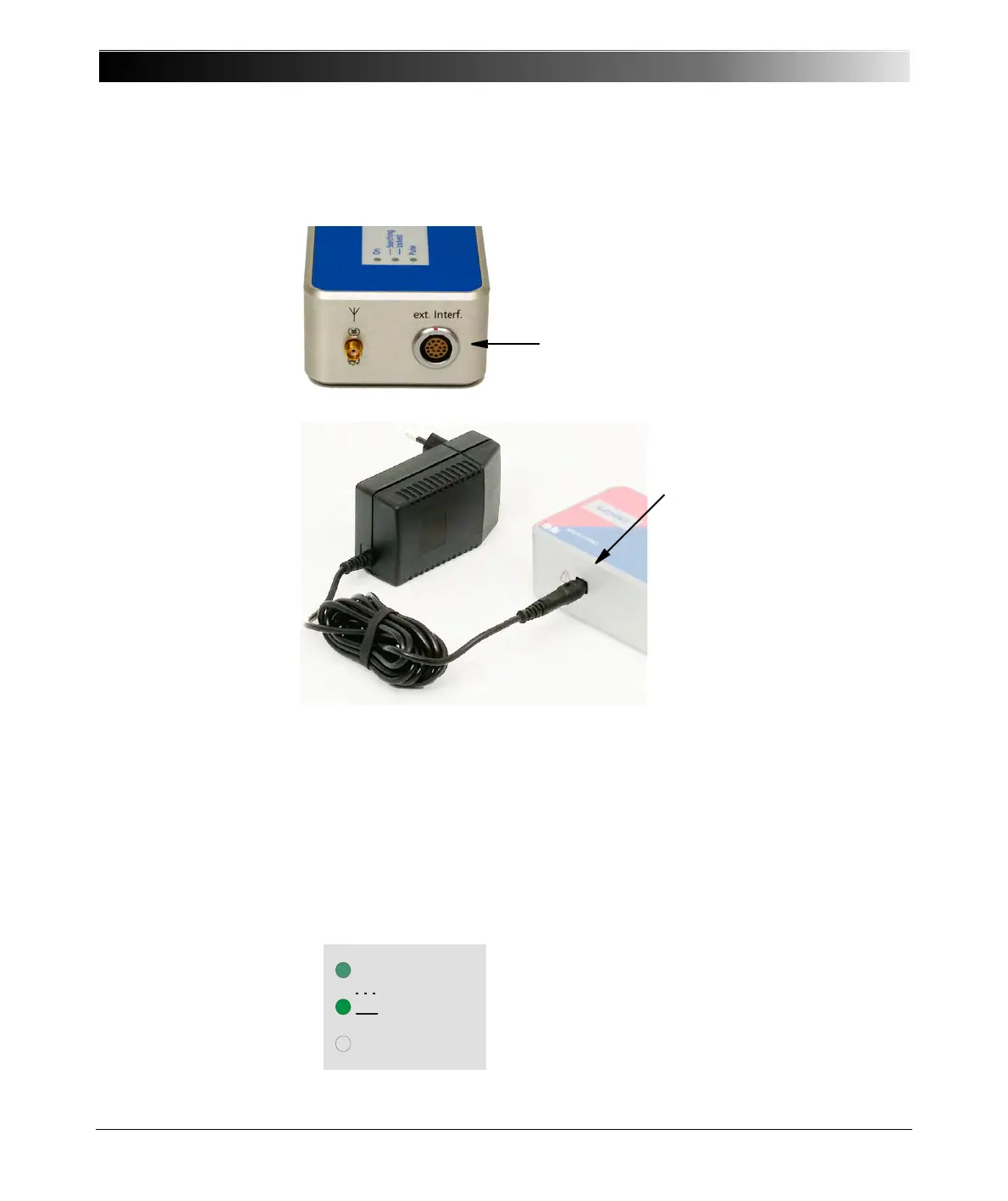
Figure 4-2:
Power supply unit
100 - 240 VAC/18 VDC
incl. plug-in adapter for
country-specific wall
outlets
1. Section 3.2 ”LED Status Display” on page 17 describes the state of the LED
signalization during the activation and initialization of the CMGPS.
The following explanations are based on successful initialization and on the
fact that the CMGPS locked itself to the GPS signal.
The state of the LEDs of the CMGPS should then be as follows:
1. Connect the ext. Interf. of the CMGPS to
the ext. Interf. input at the rear of the CMC
test set by means of the supplied
connection cable VEHK0003 (shown in
figure 3-3).
2. Plug in the DC adapter of
the 100-240 V
AC
/18 V
DC
power supply unit to the
DC in power supply input of
the CMGPS.
3. Connect the power supply
unit to a wall outlet.
Note: The power supply
unit is not needed with up-
to-date test sets such as
CMC 256, CMC 256plus,
CMC 353, CMC 356 and
CMC 850. In conjunction
with the CMIRIG-B interface
unit, use the above
mentioned power supply
unit to power the CMGPS.
On
Pul se
Sea r c h i n g
Lo c k ed
LED "ON" is lit.
LED "Searching/Locked" is lit.