EasyManuals Logo

Omicron CT Analyzer User Manual

Omicron CT Analyzer
28 pages
To Next Page IconTo Next Page
To Previous Page IconTo Previous Page
Page #18 background imageLoading...
Page #18 background image
Getting Started with CT Analyzer & CT SB2
18 OMICRON
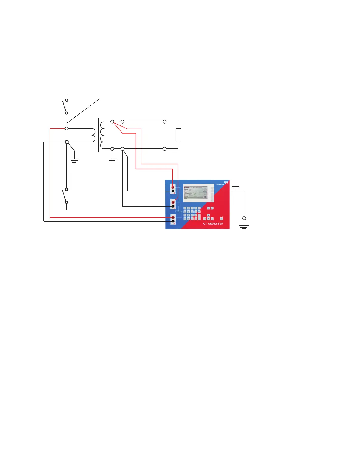
5. Connect the red "Output" socket and the red socket of input "Sec" of the CT Analyzer to the other
(ungrounded) terminal on the secondary side of the CT.
Figure 3-1: Basic wiring for a CT test
Note: The CT may make humming or buzzing noises of varying frequency during the CT test. This is
completely normal and does not indicate a defective CT.
Utility line
Prevent coupling of interferences into the primary circuit (e.g. by disconnecting the utility line,
switching off the breaker, etc). Coupling of interferences into the ungrounded connection influences
the measurement results.
The side that is able
to receive more
interferences has to
be connected to PE.

Questions and Answers:

Question and Answer IconNeed help?

Do you have a question about the Omicron CT Analyzer and is the answer not in the manual?

Omicron CT Analyzer Specifications

General IconGeneral
TypeCT Analyzer
Measurement CategoriesCAT III 300 V
Power Supply100-240 V AC, 50/60 Hz
Primary ApplicationTesting and calibrating current transformers
InterfaceUSB, Ethernet
StandardsIEC 60044-1
Voltage Range0 to 300 V
Accuracy±0.02%
Basic Accuracy0.02% (typical)

Related product manuals