OMICRON 23
Technical data of the CT Analyzer
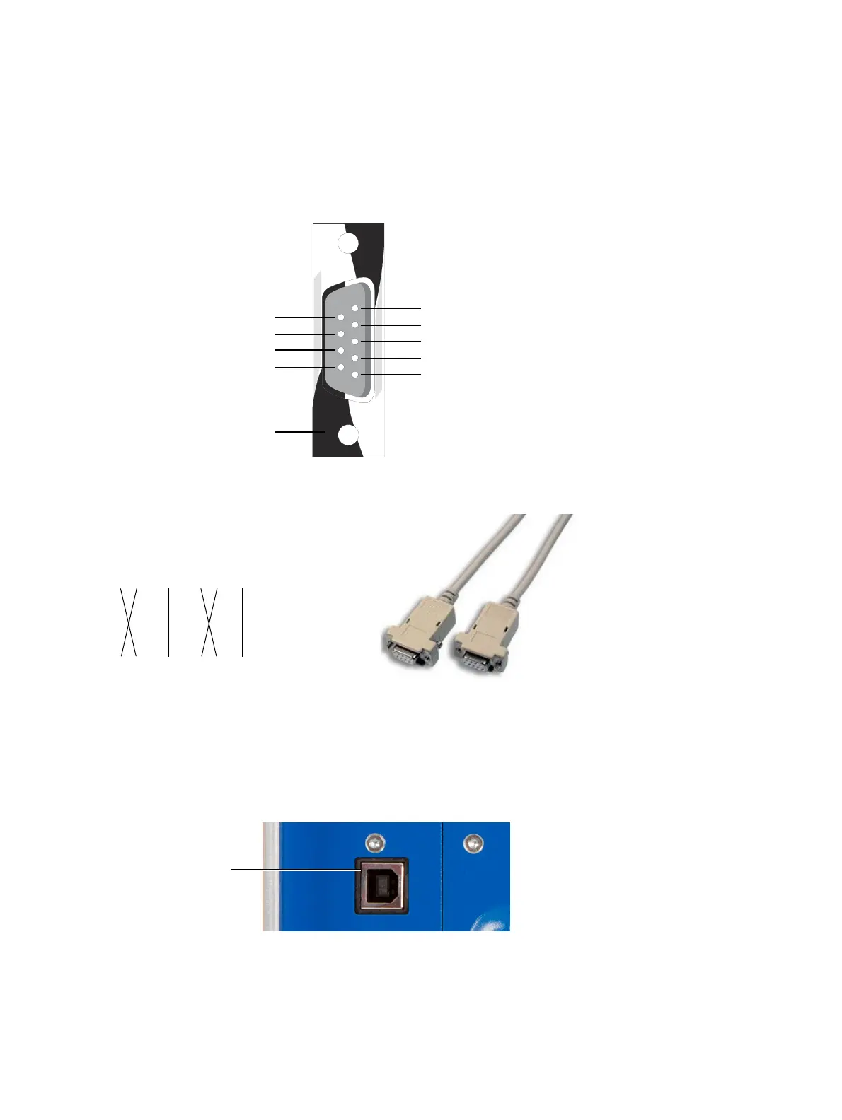
4.7.1 RS232 interface
The RS232 interface can be used to connect the CT Analyzer to a computer or to the optional CT SB2
switch box.
Figure 4-1: Pin assignment for RS232 remote control interface
Figure 4-2: Connection cable for RS232 remote control interface
4.7.2 USB interface
The USB interface can be used to connect the CT Analyzer to a computer. Communication via USB is
considerably faster than communication via RS232.
Figure 4-3: USB remote control interface (standard type B connector)
1nc
2 RxD (data in / receive)
3 TxD (data out / transmit)
4nc
5 GND (signal ground)
6nc
7 RTS (out)
8CTS (in)
9+ 5V
Do not connect!
For internal use only!
Housing: Shield (ground)
9-pole SUB-D connector, male
Figure shows outside view
onto the pins at the CT Analyzer!
Connections required:
12345678shield
12345678shield
9-pole (DB9) null modem or
crossover cable, 2 x female
USB interface
(type B connector)