OMICRON 21
Technical data of the CT Analyzer
4.4 Winding resistance measurement accuracy
4.5 Ratio and phase measurement accuracy
The values given in the following table are only valid under the following conditions:
• All utility lines to the primary side of the CT are disconnected.
• One terminal of the primary side of the CT is connected to PE.
• The original measurement cables delivered by OMICRON for the CT Analyzer are used.
• The CT under test is a CT with a non-gapped core.
• The knee point voltage according to IEEE C57.13 is > 3V.
Under interfering conditions the device has reduced accuracy.
Values without the prefix "!" in the ratio table of the Ratio card have guaranteed accuracy. The accuracy
of values marked with a "!" in the table is reduced by factor 2 since these values are not directly
measured but calculated from the measured values instead.
Table 4-4: Measurement input "Prim"
Characteristic Rating
Voltage ranges 0 - 0.03 / 0.3 / 3 / 30V
AC
(auto ranging)
Accuracy 0.1% (guaranteed)
Insulation Reinforced insulation (R) to all other circuits
Table 4-5: Winding resistance measurement accuracy
Characteristic Rating
Resolution
1m
Ω
Accuracy 0.05% (typical)
0.1% + 1m
Ω (guaranteed)
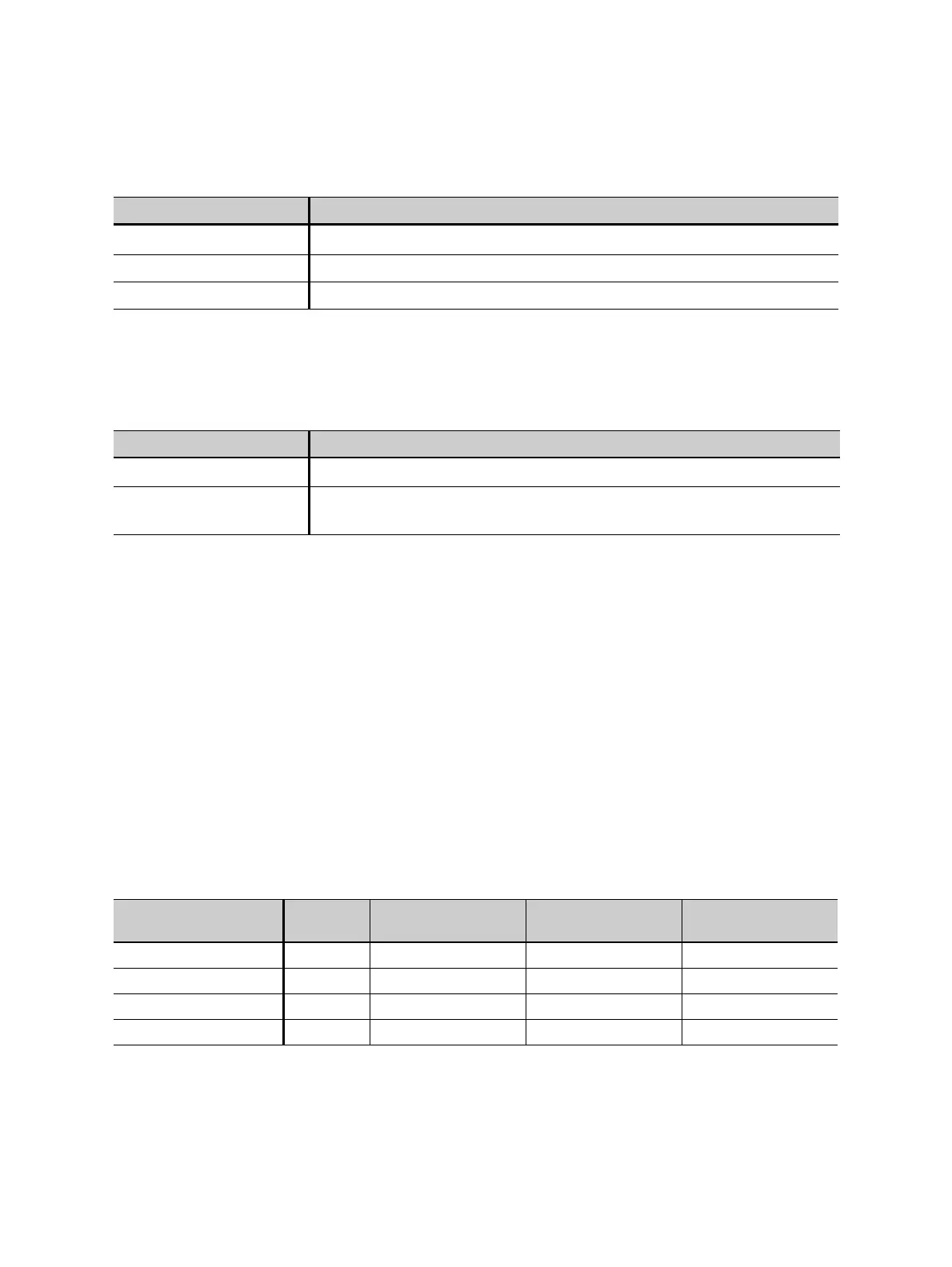
Table 4-6: Ratio measurement accuracy for 1 A CTs at rated current
CT ratio I
sn
Rated power
1
1. Nominal burden of the CT.
Typical accuracy Guaranteed
accuracy
0.2 - 1 1 1.0 - 30VA 0.05% 0.1%
> 1 - 2000 1 0 - 30VA 0.02% 0.05%
> 2000 - 5000 1 0 - 30VA 0.03% 0.1%
> 5000 - 10000 1 0 - 30VA 0.05% 0.2%