OMICRON 19
Setup and connection
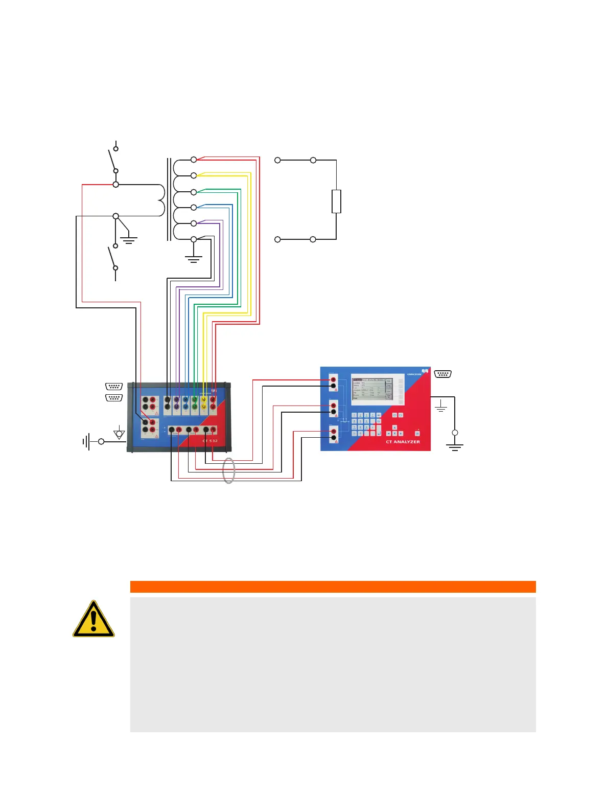
3.4 Basic measurement setup for multi-ratio CT testing
Figure 3-2: Basic measurement setup for multi-ratio CT testing (6 tap CT, no burden measurement, no
primary winding resistance measurement)
WARNING
Death or severe injury caused by high voltage or current possible
Feeding test voltage to a CT can cause life-threatening voltages on other taps and/or
cores of the CT.
► Do not touch other taps or windings of the CT during the test.
► When testing multi-core CTs, make sure that no other windings of the CT are open.
Leave the secondary windings of the other (non-measured) cores connected, or short-
circuit them if the windings are open.
► Always connect all secondary taps/windings to the CT SB2 switch box in order to
guarantee safety during testing.
Burden
CT
* For information how to connect the communication link between the CT SB2 and the CT Analyzer, please refer to the CT SB2
User Manual.