EasyManuals Logo

Omicron CT Analyzer User Manual

Omicron CT Analyzer
28 pages
To Next Page IconTo Next Page
To Previous Page IconTo Previous Page
Page #11 background imageLoading...
Page #11 background image
OMICRON 11
Introduction
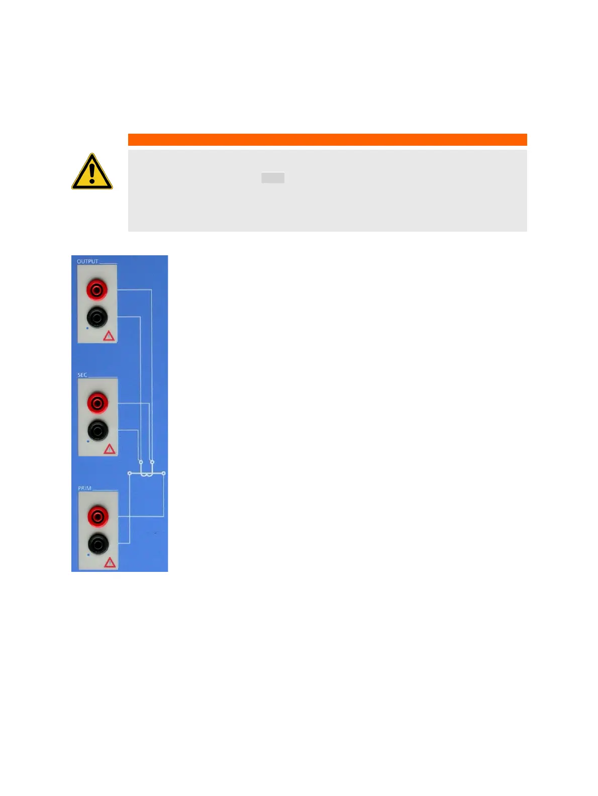
2.4.2 Inputs and outputs
Figure 2-2: Inputs and outputs of the CT Analyzer
WARNING
Death or severe injury caused by high voltage possible
As long as the red LED of the key is flashing, the output is active and lethal voltages
can occur due to the high energy stored in external inductors.
Do not touch the test object or the measurement leads while the red LED is flashing.
Wait until the LED is off before touching the measurement setup.
I/0
Output
Generator output.
AC: 40V
rms
, 5A
rms
DC: 120V, 5A (15A
peak
)
Sec
Measurement input for secondary side of CT, 300V
AC
max.
Prim
Measurement input for primary side of CT, 30V
AC
max.

Questions and Answers:

Question and Answer IconNeed help?

Do you have a question about the Omicron CT Analyzer and is the answer not in the manual?

Omicron CT Analyzer Specifications

General IconGeneral
TypeCT Analyzer
Measurement CategoriesCAT III 300 V
Power Supply100-240 V AC, 50/60 Hz
Primary ApplicationTesting and calibrating current transformers
InterfaceUSB, Ethernet
StandardsIEC 60044-1
Voltage Range0 to 300 V
Accuracy±0.02%
Basic Accuracy0.02% (typical)

Related product manuals