16
The installation technician is responsible for selecting a cable with the
appropriate length and cross section.
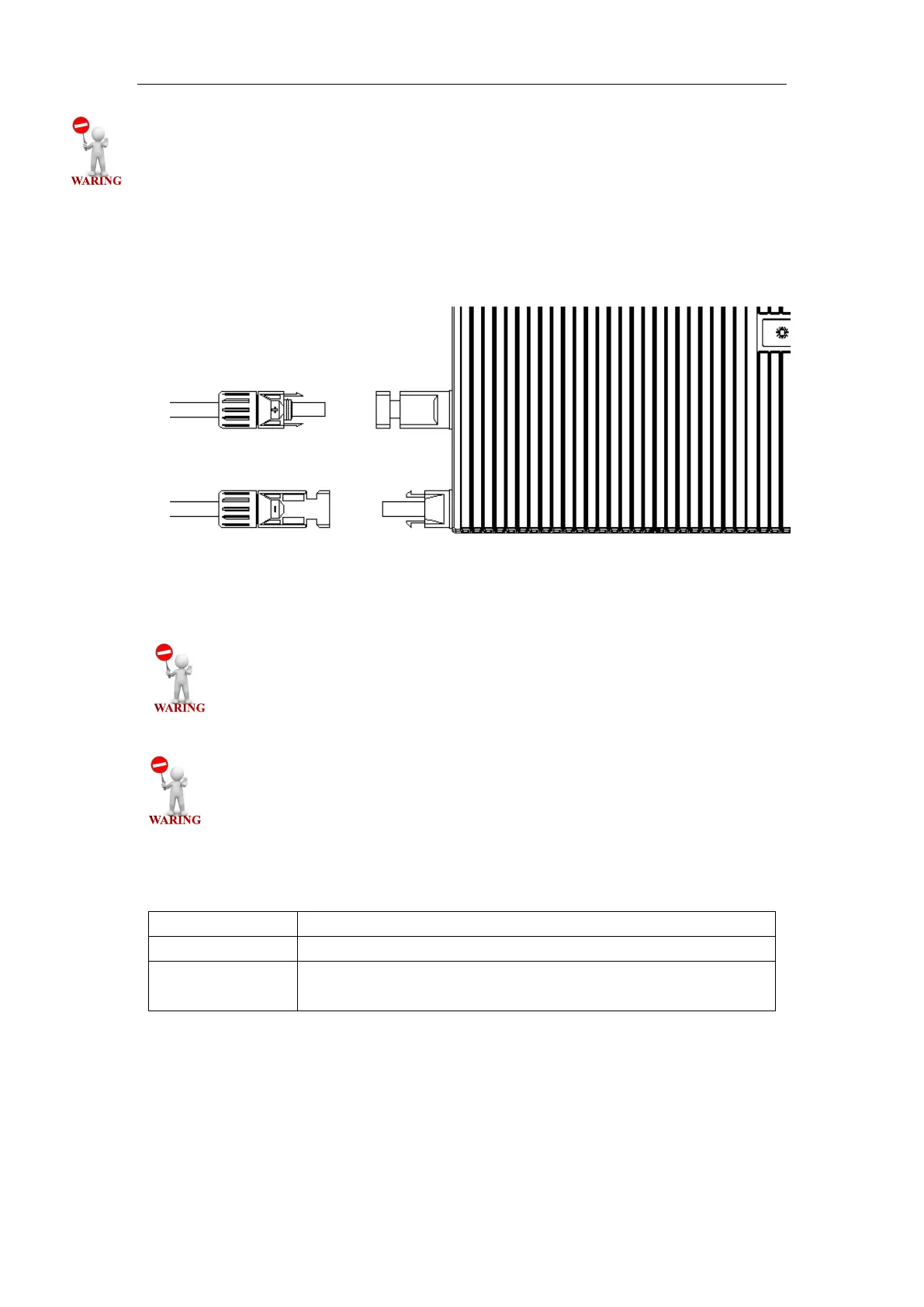
Step 3. Install Photovoltaic Modules
Install the photovoltaic modules, and connect the DC cables of the modules to the
corresponding DC input side of the Micro-inverter.
Fig.16. Connect DC Cables
The recommended installation needs keeping the Micro-inverters
underneath the photovoltaic modules, so that the Micro-inverters can
operate in the shade. Direct sunlight may cause damage to the Micro-
inverters.
Each module must be connected to the Micro-inverters with a DC
cable having a length of less than 3m.
Check the LED on the side of the micro-inverter. The LED flashes green and red at
start up.