18
6.2.2. Assembly instruction
Step 1. Install Micro-inverter
Mark the approximate center of each photovoltaic module on the frame and
install the Micro-inverter with the LED side facing upwards.
Observe the certification documents concerning the maximum
number of Micro- inverters permitted for installation at each cable
section!
Numbers for each cable section
The Micro-inverter must be under the module, out of long-term
exposure to direct sunlight or rain.
Make sure the installation position of micro-inverter meet the
requirements of AC cables.
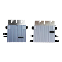
First Type of Installation (Wall bracket hole):
There are two wall bracket holes in each Micro-inverter as shown in Fig.1 and
Fig.2.Use a pair of screws and nuts to install the micro-inverter onto the bracket as
shown in Fig.20.