Omnitronix DL100 User’s Manual
Page 8
2.2 - Parts Identification
Standard Equipment
The base DL100 comes with the following standard onboard equipment:
• 2 DB9 male RS-232 serial ports
• 12VAC power
• Internal battery backup
In addition to the above components, the standard unit is shipped the following accessories:
• This product manual
• 1 Female DB9 to Female DB9 null modem serial cable
• Power supply (not included for –48VDC equipped units)
Each of the following components is optional and may be installed on a DL100:
• 2 additional male DB9 RS-232 serial ports
• Ethernet adapter
• 33.6Kbps modem or external modem adapter
• -48VDC power receptacle, no power supply
• 5VDC power receptacle and power supply
The DL100 may come with any of the following accessories as well, depending on the
configuration or order:
• Additional Female DB9 to Female DB9 null modem serial cable
• Female DB9 to male DB25 serial cables
• 19 inch 1U rack mount adaptor flanges
• Omnitronix Alarm Manager software
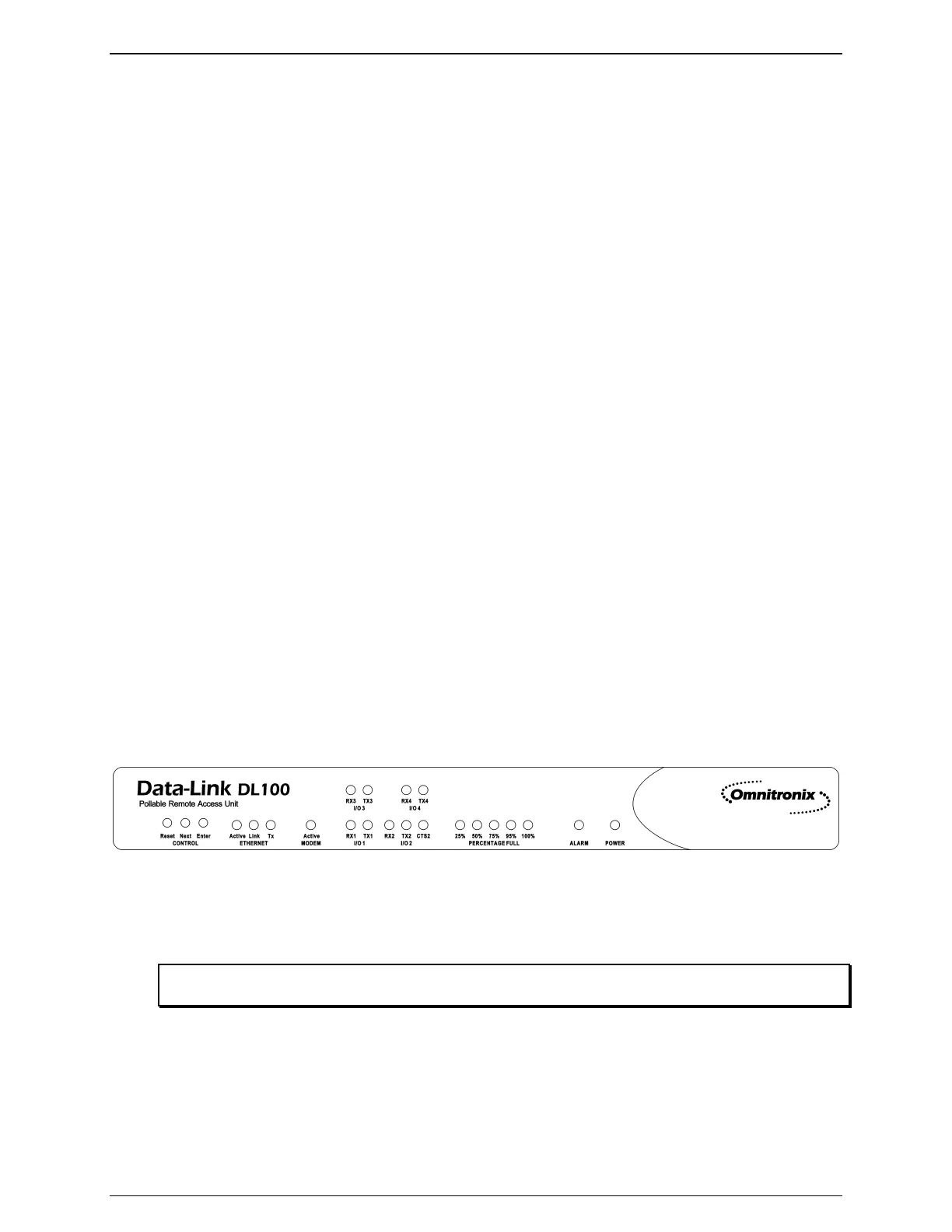
2.3 - Front Panel
Figure 3: DL100 Front Panel
The front panel of the DL100 carries 3 push buttons and 22 LED indicators. This section will
explain the function of each of these indicators.
Note: The Next and Enter buttons on the front panel have no current functionality and are reserved for
future use.
The Ethernet status is shown as three LEDs. The Link LED lights whenever an Ethernet 10BaseT
network link connection is found. The yellow TX LED lights briefly whenever an Ethernet frame
is being transmitted. The Active LED lights whenever a network connection, such as ftp, Telnet,