Chapter 2 - What is a DL100?
Manual Rev. 1.02 Page 11
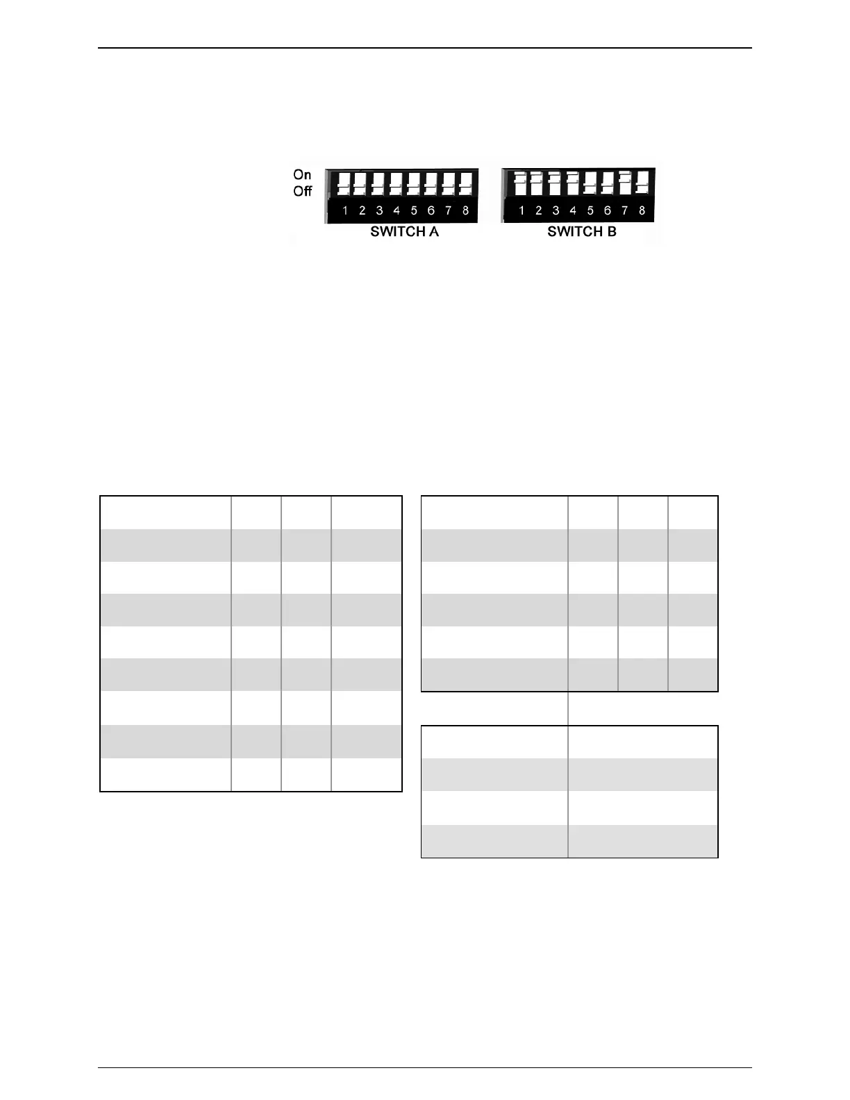
Dipswitches
The back of the DL100 is equipped with two banks of eight Dipswitches each:
Figure 7: Dipswitch Orientation
Please refer to the following for the functionality of each switch:
• Switches A1 through A3 and B1 through B3 configure baud rate for I/O1 and I/O 2,
respectively (see table below)
• Switches A4 through A6 and B4 through B6 configure word length, parity, and stop bits for
I/O1 and I/O 2, respectively (see table below)
• Switch A7 is reserved and is to remain off at all times
• Switch A8 is reserved for future use
• Switches B7 and B8 determine the operating mode of I/O 2 (see table below for details)
The following table outlines the functionality of Dipswitches B1 through B6 in switching the baud
rate and port settings of I/O 2.
Baud Rate SW1 SW2 SW3 Word, Parity, Stop SW4 SW5 SW6
9600 OFF OFF OFF 7 Bits None 1 OFF OFF OFF
300 OFF OFF ON 7 Bits Even 1 OFF OFF ON
600 OFF ON OFF 7 Bits Odd 1 OFF ON OFF
1200 OFF ON ON 7 Bits None 1 OFF ON ON
2400 ON OFF OFF 8 Bits None 1 ON OFF OFF
4800 ON OFF ON
9600 ON ON OFF I/O 2 Mode B7 B8
19200 ON ON ON Command Mode OFF OFF
Inline Mode OFF ON
Input Mode ON ON
2.5 - Functionality Overview
The DL100 is designed to perform several functions key to the Data-Link family while offering
greater value to users who do not need the full range of functionality offered by the Data-Link
DL880. The features of the DL100 are covered in the following subtopics.