Omnitronix DL100 User’s Manual
Page 38
• If any rule is violated in a equation, an alarm will not be generated, nor will an error be
presented
Note: There may be times when two or more fields are necessary to analyze one piece of data. For
example, if a time is represented in hh:mm format, certain calculations may require two different
fields. Other times, wildcards will do the job of masking out non-important characters just fine.
Do not hesitate to use multiple fields and wildcards to make equations as powerful as necessary.
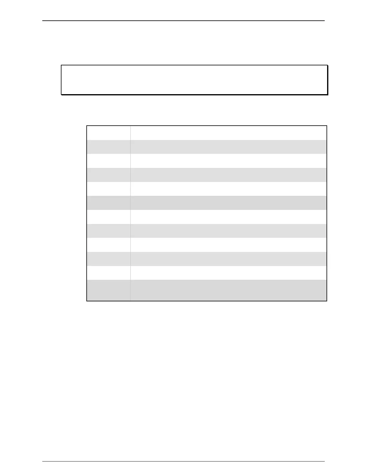
The data alarm equations used in the DL100 are standard Boolean-type operators. The following
table outlines each of the supported operators and their function.
Operator Function
> Greater Than
< Less Than
>= Greater Than or Equal to
<= Less Than or Equal to
! or <> Not Equal to
= Equal to
* Single character wildcard (matches any character or space)
() Parenthesis used to combine operations
OR Logical OR
AND Logical AND
@ Positional wildcard (used in place of a field name to match anywhere
within an incoming record)
Figure 10: Alarm Equation Operators
5.3 - Creating a Data Alarm Monitor
Configuring a Data Alarm Field
Creating the data fields is a simple matter of defining which parts of incoming records to search
for alarm data. The following steps will walk you through this process.
1. Proceed to the Setup Alarm Fields menu.
2. Select the first empty alarm field.
3. Enter "1" for the start position.
4. Enter "6" for the field length.
5. Name the field “Test_Field”.