Manual Rev. 1.02 Page 3
Chapter 1
Quick Start Guide
1.1 - Introduction
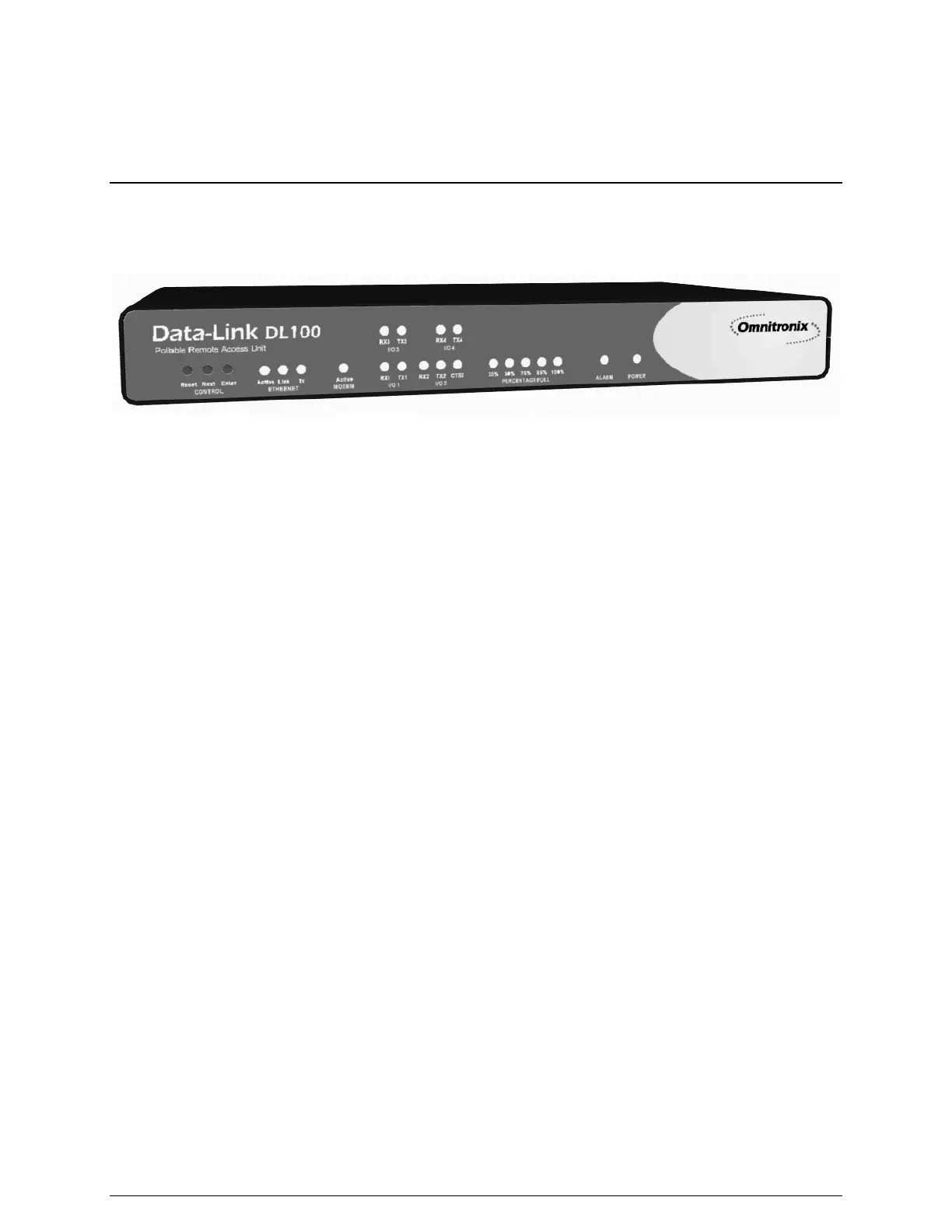
Figure 1: The Data-Link DL100
This chapter will highlight the setup and configuration of an example Data-Link DL100. Areas of
setup and configuration covered in this chapter include physical setup, connecting to the DL100,
networking, and data alarm monitoring.
Hardware Checklist
• Omnitronix Data-Link DL100
• Computer with male DB9 RS-232 Serial port and terminal emulation software
• Ethernet Connection
• Power adaptor (Included with 5VDC and 12VAC units)
• Female DB9 Null Modem serial cable (Included)
• PC running Omnitronix AlarmManager software (Software may be obtained at
http://www.omnitronix.com or by contacting Omnitronix Technical Support)
Data checklist
• Static IP address to assign to the DL100
• Subnet mask
• Default router IP: Optional
• Gateway router IP address, if on a WAN
• IP address of the PC running AlarmManager
1.2 - Connecting to the DL100
Cables and Power
1. Connect one end of the DB9 cable to I/O 2 of the DL100 and the other into COM1 of the
computer with a terminal emulator.
2. Connect the power supply cable into the unit and the transformer into an appropriate power
receptacle.
3. Connect an Ethernet cable, if available, into the RJ-45 jack labeled Ethernet.