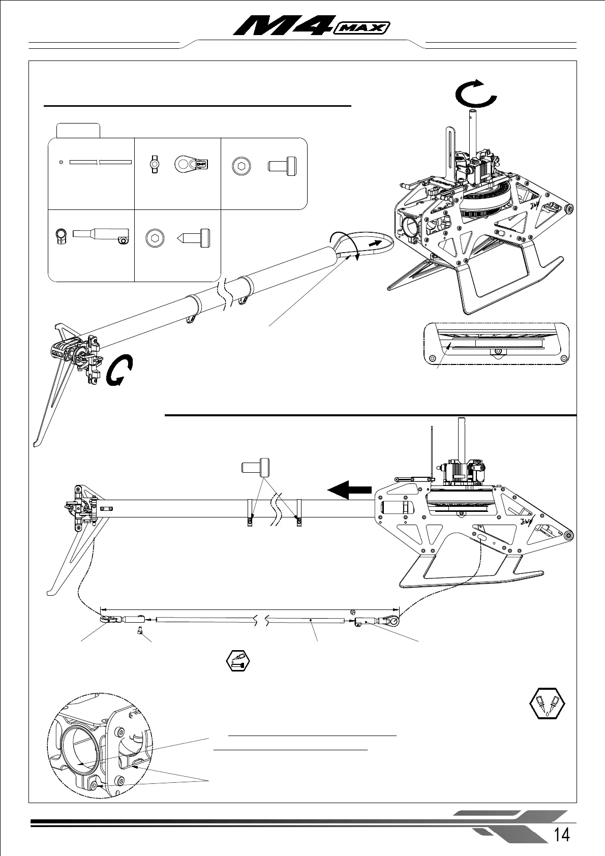
3-3 Tail boom, tail servo linkage rod assembly
※ Pay close attention to the twist direction of
the belt. The belt should be pulled straight
through the boom. Rotate the free end 90° as
shown to achieve proper tail rotor rotation. Do
not twist the belt further than 90° .
The tail boom can be pushed further
inward to give the belt more slack for
installing it onto the main pulley.
X Tail servo linkage rod (× 1)
4.5 linkage ball set (M2.5 ) (× 2)
X Control Rod Joint (× 2)
※ After the tail belt is tensioned, tighten the
two clamping screws left loose in step 2-2 to
secure the boom in place .
※ The control rod ends should be sand and glued onto the carbon rod with AB glue/Epoxy, avoid
using Superglue/CA. Pay attention to the correct rod length.
※ Use sand paper on the rod ends to roughen them and make insertion into the joint easier.
Pull the tail boom backwards to tension the belt, to ensure that the flying power is effectively
transmitted to the tail. Do not over-tighten the belt to avoid excessive drag, but do not
over-loosen it, as too much looseness will cause the belt to jump, vibrate, and wear out.
After installation the rotary drive runs smoothly and the tensioner pulley rotates normally
with the timing belt
Different types of servos require different linkage rod lengths, with micro servos
needing approximately 584mm, and mini servos requiring about 589mm
M4X-303
4.5 linkage ball set
(M2.5 ) (× 2)
X Tail servo linkage
rod (× 1)
X Control Rod Joint (× 2)
14
WWW.OMPHOBBY.COM
Installation steps 安装步骤
A
B
Socket cap screw
M 1.6 x 3 mm (× 2)
Lock the M2x6 screws to the tail rod limiters
after attach the X tail servo linkage
Socket cap screw
M1.6x3mm ( × 2)
Self-tapping screws
M2x6mm ( × 2)
※ Here to put on some grease onto the
rubber ring for easier installation.