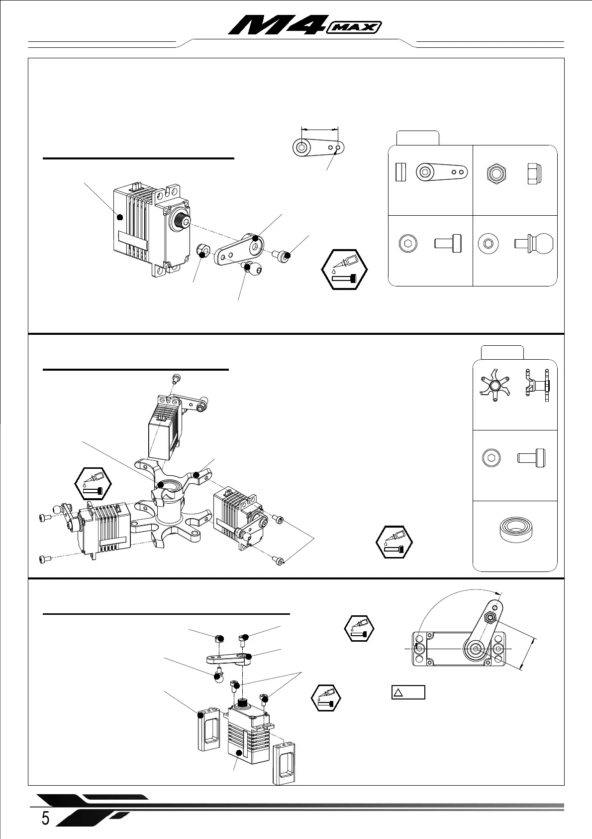
1-1 Cyclic Servo Assembly
Servo Swashplate (× 3)
Servo Arm (× 3)
Socket cap screw
M2x4mm ( × 3)
Ball Joint Screw - L4.65 (× 3)
M2 Nylon locknut (× 3)
Servo Arm (× 3)
Socket cap screw
M2x4mm ( × 3)
Ball Joint Screw - L4.65 (× 3)
M2 Nylon locknut (× 3)
Socket cap screw
M2x4mm ( × 6)
M4X-101
M4X-102
Servo Rack ( × 1)
Servo Rack ( × 1)
Socket cap screw
M2x4mm ( × 6)
1-2 Servo Rack Assembly
1-3 Tail servo (Micro servo ) assembly
※
The ball joint screw should be screwed
into the outer hole of the servo arm.
5
WWW.OMPHOBBY.COM
Installation steps 安装步骤
Bearing ∅ 8x ∅ 14x4mm ( × 2)
Bearing ∅ 8x ∅ 14x4mm ( × 2)
※ Note: All servo wires shou ld exit the servo rack
in one position , which should be aligned with the
rear of the frame .
Partially pre-assembled parts are loosely screwed together without thread locker/glue
Recommendation: Loctite 243 for screws, Loctite 648 for bearing seats.
※ Note: In a crash, the servo arm spline can strip.
※ The servo wires can be wrapped around the
core of the servo rack to shorten them neatly.
16mm
115°
M2 Nylon locknut (× 1)
Tail servo (× 1)
Tail servo mount set (× 2)
Servo Arm (× 1)
Socket cap screw
M2x4mm ( × 2)
Socket cap screw
M2x4mm ( × 1)
Ball Joint Screw - L4.65 (× 1)
!
注意
CAUTION
The maximum height of the tail servo, including servo
arm, must be less than 40. 0mm. When the tail servo
arm is in the middle position, the angle relative to the
tail servo should be 115°, as shown above.
※ The M4 Max can be equipped with the
DS2312T micro servo, and the ball head screw
should be installed in the outer hole of the servo
arm. The manual will provide an illustrative
installation diagram for the mini servo, and the
installation method for the micro servo is the
same as that for the mini servo.
12.5mm