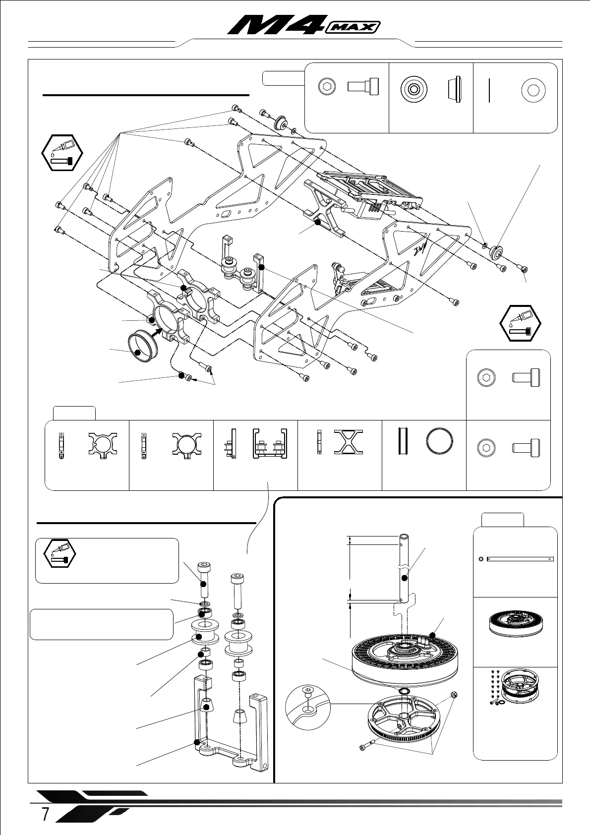
2-2 Main frame set assembly
X Brace (×1)
Socket cap screw
M 2.5 x 5 mm (× 16 )
X Tail Boom
Mount ( × 1)
X Square Frame
Brace ( × 1)
X-Brace (×1)
Socket cap screw
M 2.5 x 5 mm (× 16 )
2-3 Motor assembly
Main Pulley ( × 1)
Main Rotor
Shaft ( × 1)
7
WWW.OMPHOBBY.COM
Main Rotor Shaft ( × 1)
Main Pulley ( × 1)
countersunk head hexagon socket
screw M2x3mm ( × 12)
Main Pulley Flanges ( × 2)
Socket cap screw M2.5x15mm ( × 1)
Nyloc Nut M2.5 (× 1)
Shim ∅ 8x ∅ 10x0.2mm ( × 1)
Socket cap screw
M 2.5 x 8 mm (× 2 )
※ Do not tighten the M2.5x8mm clamping screws on the tail boom mounts .
※ The clamping screws should be inserted from right side to prevent interference with the tail
rotor linkage.
Socket cap screw
M 2.5 x 8 mm (× 2 )
Installation steps 安装步骤
Socket cap screw
M3x16mm ( × 2)
Bearing ∅ 3x ∅ 6x2.5mm (× 4)
X Idler Pulley ( × 2)
X Bushing ∅ 3x ∅ 4x2 (× 2)
X Idler Cone ( × 2)
Square Brace (× 1)
Square Frame Brace Assembly
Shim
∅ 2.5x ∅ 5x0.5mm ( × 2)
Canopy frame
support rubber ( × 2)
Step socket cap screw
M2.5x6mm (× 2 )
Step socket cap screw
M2.5x6mm (× 2 )
Canopy frame support
rubber ( × 2)
Shim
∅ 2.5x ∅ 5x0.5mm ( × 2)
※ Note that the main
pulley flange carbon
plates are recessed one
side to suit countersunk
screws.
Shim ∅ 3.05x ∅ 4.5x0.5mm ( × 2)
(Already installed with retaining compound)
(Already installed with retaining compound)
X Square Frame Brace ( × 1)
X Tail Boom Mount convex ( × 1)
M4X-202
M4X-202
X-fixed seat gasket
(× 1)
X Tail Boom Mount ( × 1) X-fixed seat gasket ( × 1)
X Tail Boom
Mount convex
(× 1)
SUNNYSKY
8110 Motor ( × 1)
M4X-203
SUNNYSKY 8110 Motor ( × 1)
3mm
7.5mm
Shim
∅ 8x ∅ 10x0.2mm
(× 1)