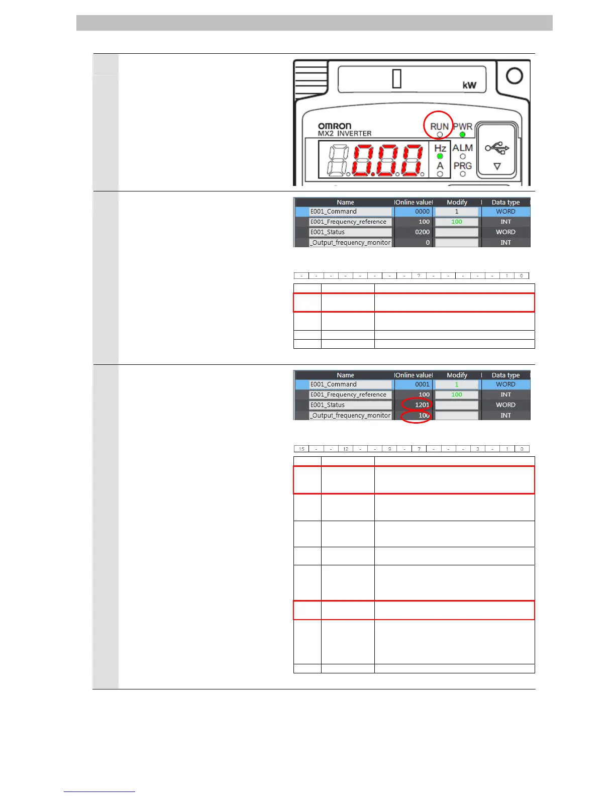
Check that the RUN LED indicator
on the Inverter is unlit and the
7-segment display (Output
frequency) is "0.00".
10
Enter "1" in the Operation command
to Inverter: E001_Command.
*Command bit 0: Forward/stop
0:Stop
1:Forward command
Command
Bit Name Meaning
0 Forward/stop
0:Stop
1:Forward command
1 Reverse/stop
0:Stop
1:Reverse command
7 Fault reset Resets an error or trip for the unit or Inverter.
- (Reserved) The reserved area. Set 0.
11
Check that Status:E001_Status is
“1201” and Output frequency
monitor:E001_Output_frequency_m
onitor is “100”.
*Status bit 0: Forward Operation in
progress
0:Stopped/during reverse
operation
1:During forward operation
*Status bit 12: Frequency matching
0:During
acceleration/deceleration
1:Frequency matching
Status
Bit Name Meaning
0
Forward
operation in
progress
0:Stopped/during reverse operation
1:During forward operation
1
Reverse
operation in
progress
0:Stopped/during forward operation
1:During reverse operation
3 Fault
0:No error or trip occurred for the unit or
Inverter
1:Error or trip occurred for the unit or Inverter
7 Warning
0:No warning occurred for the unit or Inverter
1:Warning occurred for the unit or Inverter
9 Remote
0:Local (Operations from EtherCAT are
disabled)
1:Remote (Operations from EtherCAT are
enabled)
12
Frequency
matching
0:During acceleration/deceleration
1:Frequency matching
15
Connection
error between
the Optional
Unit and
Inverter
0:Normal
1:Error (Cannot update data for the Inverter. To
restore, turn the power OFF and then ON
again.)
- (Reserved) The reserved area.
28

 Loading...


