E-8 Conductive Level Controller 61F-GP-N8
Connections
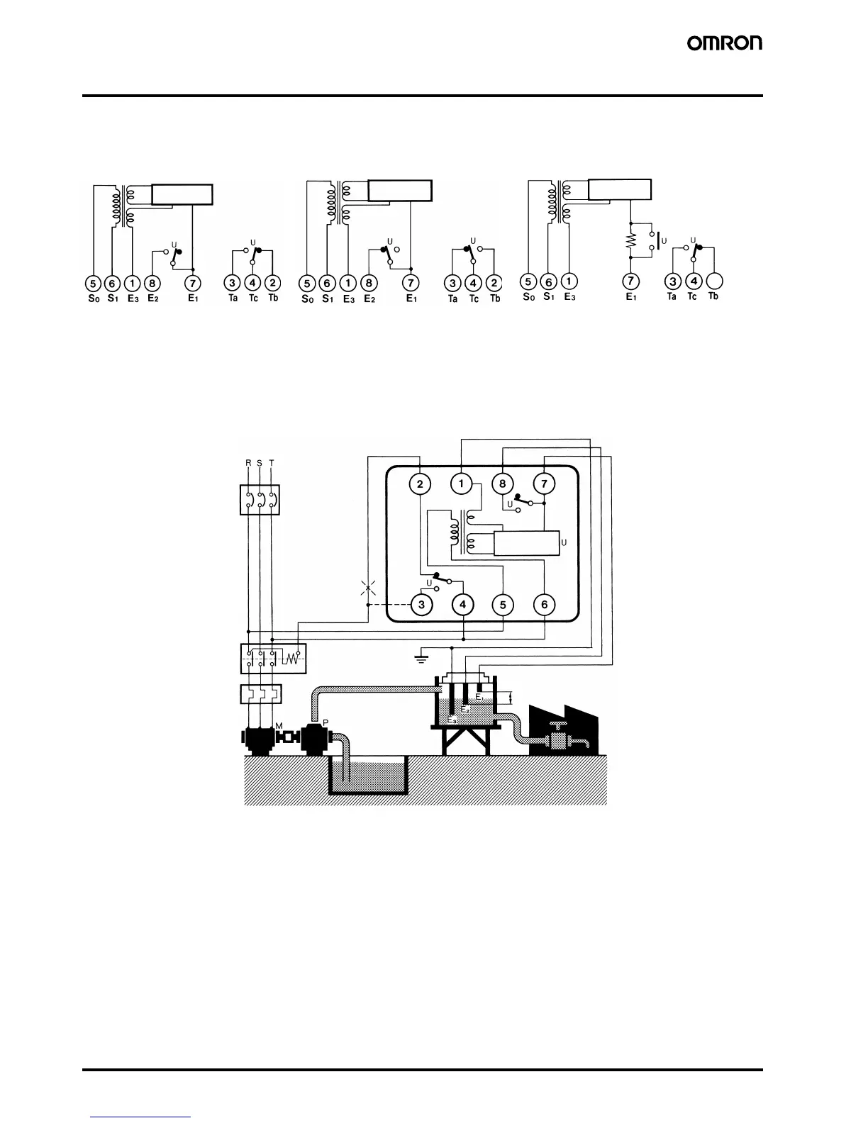
■ Internal Circuit Diagrams
■ Automatic Water Supply and Drainage Control
1. Water Supply
• Connect electromagnetic switch coil terminal A to terminal 2.
• The pump stops when the water level reaches E1 and starts when
the water level drops below E2.
2. Drainage
• Connect the electromagnetic switch coil terminal A to terminal 3.
• The pump starts when the water level reaches E1 and stops when
the water level drops below E2.
Note: 1. The diagram shows the connections for water supply. When draining, change the connection from terminal 2 to terminal 3.
2. The earth terminal must be earthed.
24 V
24 V
24 V
24 V
8 V
2
Control circuit
Control circuit
8 V (see note)
61F-GP-N8/-N8L/-N8D/-N8HY 61F-GP-N8H
61F-GP-N8R
Note: 24 V for the 61F-GP-N8HY.
Control circuit
Power
supply
Power
supply
Power
supply
0 V
200 V
8 V
24 V
61F-GP-N8
MCCB
Tank
Stop
Start
Reservoir
THR
PS-3S
200-VAC power supply
Contactor
Control circuit
(See note 1
below.)
(See note 2
below.)
 Loading...


