Conductive Level Controller 61F-GP-N8 E-9
Level
Controllers
Operation
The Conductive Level Controller consists of a plug-in controller con-
nected to a set of stainless steel probes. These are cut to length and
inserted vertically into the liquid. A low voltage is applied between
these probes and the earth probe (or tank, if it is electrically conduc-
tive). The water provides a current between the earth probe and the
high-level probe. The output relay in the Controller is energized when
the water level reaches the high-level probe and de-energized when
the water level falls below it.
For two-point control a low-level probe is used as well. In this case
the relay does not de-energize until the water level falls below the
low-level probe. Using the low-level probe allows a wide differential
between switching a pump on and off, and can avoid excessive pump
operation during tank emptying or filling. If this differential is not
required, the low-level probe need not be connected.
Surge Suppressor Unit (61F-03B/04B)
A high-capacity protective device is available which protects 61F-
series Floatless Level Controllers against faults arising from electri-
cal surges (such as indirect strokes of lightning) when the Controllers
are employed in elevated water tanks or in high-altitude locations.
Specifications
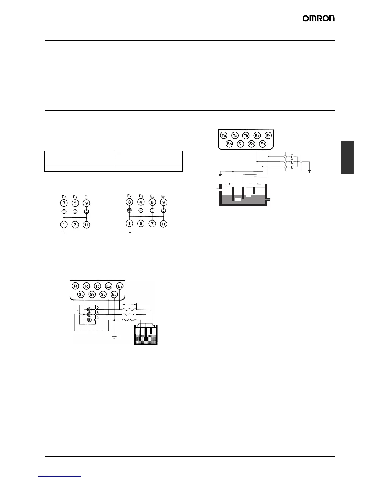
Internal Connections
Precautions
1. Mount the Surge Suppressor Unit as close to the Controller as
possible.
2. When grounding the Surge Suppressor Unit in the vicinity of the
Controller, connect the ground side of the Surge Suppressor Unit
to electrode E3.
3. When connecting the Surge Suppressor Unit, wire as shown in
the following example (with three electrodes).
Connection Sockets
PF113A-E Track-mounted Socket
PL11 Back-connecting Socket
Discharge start voltage 90 V ±20 VDC
Impulse withstand voltage 200,000 V (1 x 40 µs)
Impulse withstand current 6,000 A (1 x 40 µs)
61F-03B
61F-04B
Long distance
Ground
61F-03B
E1
E2
E3
Ground
Ground
61F-03B
 Loading...


