Conductive Level Controller 61F-GP-N8 E-7
Level
Controllers
Specifications
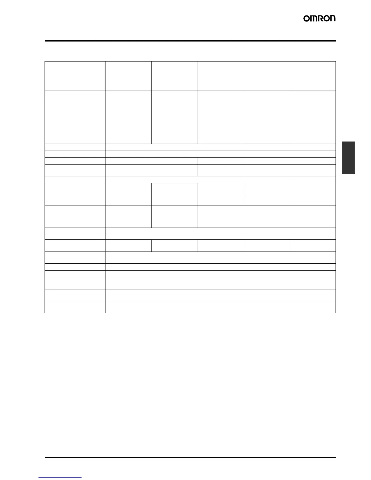
■ Ratings and Characteristics
Note: 1. The relay in the 61F-GP-N8H de-energizes when there is water present across the electrodes, whereas the relay in the 61F-GP-N8HY
energizes when there is water present across the electrodes.
2. The length when using completely-insulated, 600-V, 3-conductor (0.75 mm
2
) cabtyre cables. Usable cable lengths will become shorter
as the cable diameter or number of conductors becomes larger.
3. The insulation resistance and dielectric strength indicate values between power terminals and electrode terminals, between power ter-
minals and contact terminals, and between electrode terminals and contact terminals.
4. Possible to use with 10 kΩ or less, however, this may cause reset failure.
Model/Items General-purpose
Controller
61F-GP-N8
Long-distance
Controllers
61F-GP-N8L 2KM
(for 2 km)
61F-GP-N8L 4KM
(for 4 km)
High-sensitivity
Controllers
61F-GP-N8H
61F-GP-N8HY
(see note 1)
Low-sensitivity
Controller
61F-GP-N8D
Two-wired
Controller
61F-GP-N8R
Controlling materials and
operating conditions
For control of ordinary
purified water or sew-
age water
For control of ordinary
purified water in cas-
es where the distance
between sewage
pumps and water
tanks or between re-
ceiver tanks and sup-
ply tanks is long or
where remote control
is required.
For control of liquids
with high specific re-
sistance such as dis-
tilled water
For control of liquids
with low specific re-
sistance such as salt
water, sewage water,
acid chemicals, alkali
chemicals
For control of ordinary
purified water or sew-
age water used in
combination with two-
wired-type electrode
holder (incorporating
a resistor of 6.8 kΩ)
Supply voltage 24, 100, 110, 120, 200, 220, 230 or 240 VAC; 50/60 Hz
Operating voltage range 85% to 110% of rated voltage
Interelectrode voltage 8 VAC 24 VAC 8 VAC
Interelectrode current Approx. 1 mA AC max. Approx.
0.4 mA AC max.
Approx. 1 mA AC max.
Power consumption Approx. 3.5 VA max.
Interelectrode operate
resistance
Approx. 0 to 4 kΩ Approx. 0 to 1.3 kΩ
(for 2 km)
Approx. 0 to 0.5 kΩ
(for 4 km)
Approx. 15 kΩ to
70 kΩ
(see note 3)
Approx. 0 to 1.3 kΩ Approx. 0 to 2 kΩ
Interelectrode release
resistance
Approx. 15 k to ∞Ω Approx. 4 k to ∞Ω (for
2 km)
Approx. 2.5 k to ∞Ω
(for 4 km)
Approx. 300 k to ∞Ω Approx. 4 k to ∞Ω Approx. 15 k to ∞Ω
Response time Operate: 80 ms max.
Release: 160 ms max.
Cable length
(see note 2)
1 km max. 2 km max.
4 km max.
50 m max. 1 km max. 800 m max.
Control output 1 A, 250 VAC (Inductive load: cosφ = 0.4)
3 A, 250 VAC (Resistive load)
Ambient temperature Operating: −10°C to 55°C
Ambient humidity Operating: 45% to 85% RH
Insulation resistance
(see note 3)
100 MΩ max. (at 500 VDC)
Dielectric strength
(see note 4)
2000 VAC, 50/60 Hz for 1 min.
Life expectancy Electrical: 100,000 operations min.
Mechanical: 5,000,000 operations min.
 Loading...


