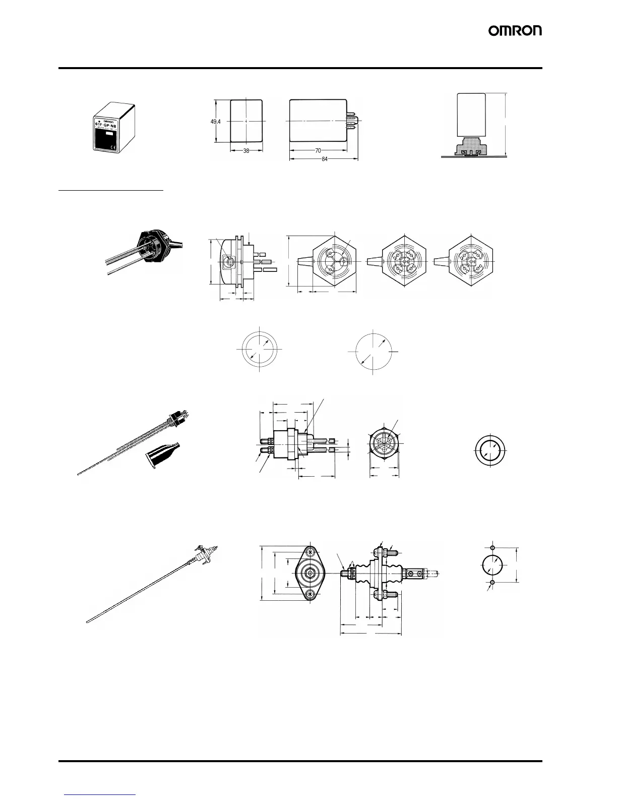
E-10 Conductive Level Controller 61F-GP-N8
Dimensions
Note: All units are in millimeters unless otherwise indicated.
Electrode Holders
PS-@S
PS-31
BF-1
91
PF083A-E
61F-GP-
N8
80
40
20
13
26
92
E2
E1
E3
E1
E3
E2
E4
E2
E3
E4
E1
PF2
80
34 dia.
65-dia. hole
Used with coupling Used with mounting bracket
PS-3S/-3SR PS-4S/-4SR PS-5S/-5SR
Mounting Holes Screw Holes
9-dia. rubber
bushing (inner)
PF2 parallel thread
(effective dia.: 58.135)
11
3
712
32
38.5
26
PF1/2
M3
Dust preventive rubber cap (optional)
11 dia.
29.5 dia.
PF1/2 Parallel thread
4 dia.
Mounting Holes
(see note)
Electrode
SUS304
Rubber
packing
Note: Standard holder construction includes three integral 300-mm-long elec-
trodes. However, a model having 1,000-mm-long electrodes is available
on request.
(49)
48
18
23
17 14
72
4860
20 dia.
Nut (M6)
Cast iron
26-dia. hole
Two, 6-dia. holes
33
dia.
Terminal bolt
SUS201 (M6)
Two M5 x 25
mounting
screws
 Loading...


