32
Group-2 High-density I/O Units and B7A Interface Units are allocated words be-
tween IR 030 and IR 049 according to I/O number settings made on them and do
not use the words allocated to the slots in which they are mounted. For 32-point
Units, each Unit is allocated two words; for 64-point Units, each Unit is allocated
four words. The words allocated for each I/O number are in the following tables.
Any words or parts of words not used for I/O can be used as work words or bits in
programming.
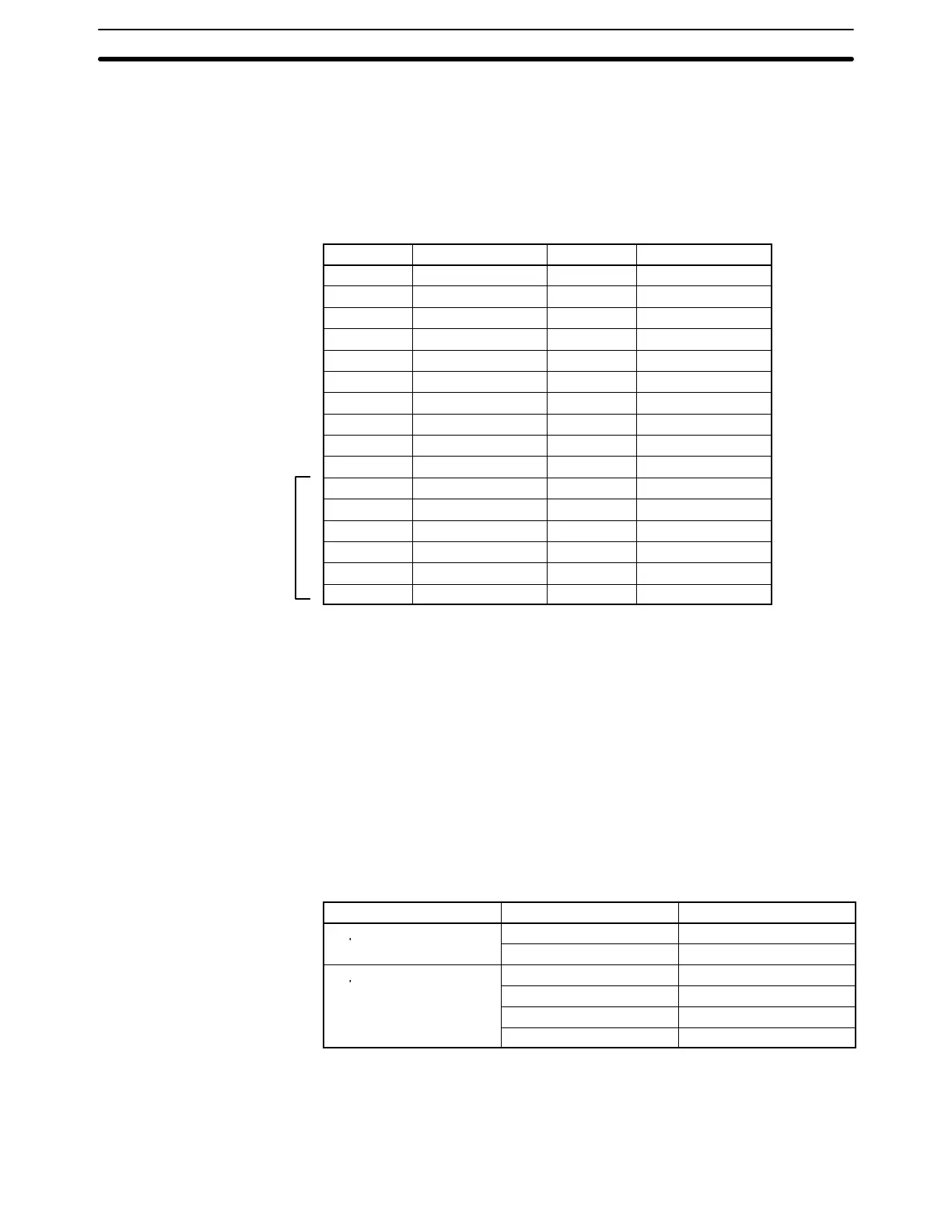
32-point Units 64-point Units
I/O number
Words I/O number Words
0 IR 30 to IR 31 0 IR 30 to IR 33
1 IR 32 to IR 33 1 IR 32 to IR 35
2 IR 34 to IR 35 2 IR 34 to IR 37
3 IR 36 to IR 37 3 IR 36 to IR 39
4 IR 38 to IR 39 4 IR 38 to IR 41
5 IR 40 to IR 41 5 IR 40 to IR 43
6 IR 42 to IR 43 6 IR 42 to IR 45
7 IR 44 to IR 45 7 IR 44 to IR 47
8 IR 46 to IR 47 8 IR 46 to IR 49
9 IR 48 to IR 49 9 Cannot be used.
A IR 330 to IR 331 A IR 330 to IR 333
B IR 332 to IR 333 B IR 332 to IR 335
C IR 334 to IR 335 C IR 334 to IR 337
D IR 336 to IR 337 D IR 336 to IR 339
E IR 338 to IR 339 E IR 338 to IR 341
F IR 340 to IR 341 F Cannot be used.
Note Unit numbers A to F cannot be set when using the following CPU Units:
C200HE-CPU32(-Z), C200HE-CPU42(-Z), C200HG-CPU33(-Z), C200HG-
CPU43(-Z), C200HX-CPU34(-Z), and C200HX-CPU44(-Z). Set unit number 0
to 9 when using these CPU Units.
When setting I/O numbers on the High-density I/O Units and B7A Interface
Units, be sure that the settings will not cause the same words to be allocated to
more than one Unit. For example, if I/O number 0 is allocated to a 64-point Unit,
I/O number 1 cannot be used for any Unit in the system.
Group-2 High-density I/O Units and B7A Interface Units are not considered Spe-
cial I/O Units and do not affect the limit to the number of Special I/O Units allowed
in the System, regardless of the number used.
The words allocated to Group-2 High-density I/O Units correspond to the con-
nectors on the Units as shown in the following table.
Unit Word Connector/row
32-point Units
m Row A
m + 1 Row B
64-point Units
m CN1, row A
m + 1 CN1, row B
m + 2 CN2, row A
m + 3 CN2, row B
Note 1. Group-2 High-density I/O Units and B7A Interface Units cannot be mounted
to Slave Racks.
2. Refer to the Installation Guide for limitations on the number of Special I/O
Units that can be mounted to Slave Racks.
Allocation for Group-2
High-density I/O Units and
B7 Interface Units
See
note.
IR (Internal Relay) Area Section 3-3