15
2-2 PC Configuration
The basic PC configuration consists of two types of Rack: a CPU Rack and Ex-
pansion I/O Racks. The Expansion I/O Racks are not a required part of the basic
system. They are used to increase the number of I/O points. An illustration of
these Racks is provided in 3-3 IR Area. A third type of Rack, called a Slave Rack,
can be used when the PC is provided with a Remote I/O System.
CPU Racks A C200HX/HG/HE CPU Rack consists of three components: (1) The CPU Back-
plane, to which the CPU Unit and other Units are mounted. (2) The CPU Unit,
which executes the program and controls the PC. (3) Other Units, such as I/O
Units, Special I/O Units, and Link Units, which provide the physical I/O terminals
corresponding to I/O points.
A C200HX/HG/HE CPU Rack can be used alone or it can be connected to other
Racks to provide additional I/O points. The CPU Rack provides three, five, eight,
or ten slots to which these other Units can be mounted depending on the back-
plane used.
Expansion I/O Racks An Expansion I/O Rack can be thought of as an extension of the PC because it
provides additional slots to which other Units can be mounted. It is built onto an
Expansion I/O Backplane to which a Power Supply and up to ten other Units are
mounted.
An Expansion I/O Rack is always connected to the CPU Unit via the connectors
on the Backplanes, allowing communication between the two Racks. Up to three
Expansion I/O Racks (two with the C200HE PCs) can be connected in series to
the CPU Rack.
Unit Mounting Position Only I/O Units and Special I/O Units can be mounted to Slave Racks. All I/O
Units, Special I/O Units, Group-2 High-density I/O Units, Remote I/O Master
Units, PC and Host Link Units, can be mounted to any slot on all other Racks.
Interrupt Input Units must be mounted to Backplanes with the “-V2” suffix on the
model number.
Refer to the C200HX/HG/HE Installation Guide for details about which slots can
be used for which Units and other details about PC configuration. The way in
which I/O points on Units are allocated in memory is described in 3-3 IR Area.
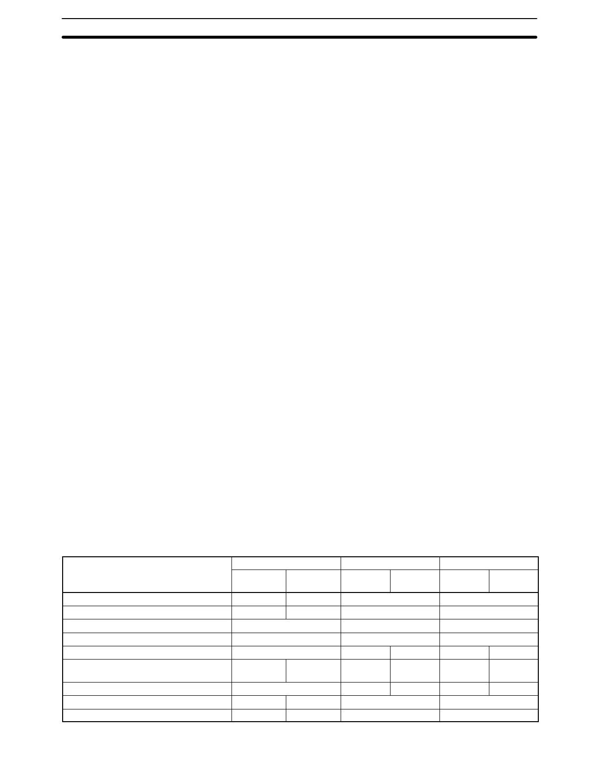
2-3 CPU Unit Capabilities
The following table shows the capabilities of the C200HX/HG/HE CPU Units.
The CPU4-E and CPU6-E CPU Units are equipped with RS-232C ports.
Item C200HE- C200HG- C200HX-
CPU11-E CPU32-E/
42-E
CPU33-E/
43-E
CPU53-E/
63-E
CPU34-E/
44-E
CPU54-E/
64-E
Program capacity 3.2K words 7.2K words 15.2K words 31.2K words
DM capacity 4K words 6K words 6K words 6K words
EM capacity None 6K words × 1 bank 6K words × 3 banks
Basic instruction execution time 0.3 μs min. 0.15 μs min. 0.1 μs min.
Max. number of Expansion I/O Racks 2 Racks 2 Racks 3 Racks 2 Racks 3 Racks
Max. number of Group-2 High-density I/O
Units
None 10 Units 10 Units 16 Units 10 Units 16 Units
Max. number of Special I/O Units 10 Units 10 Units 16 Units 10 Units 16 Units
Clock function No Yes Yes Yes
Communications Board Slot No Yes Yes Yes
CPU Unit Capabilities Section 2-3