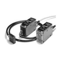
E3M-V
E3M-V
9
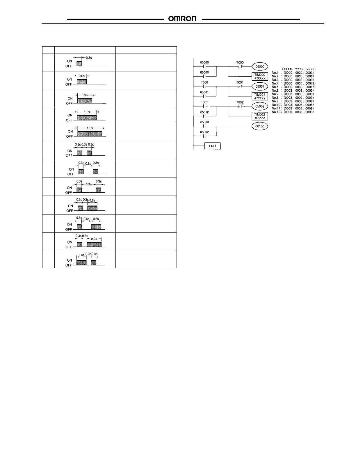
Control Signals
No.
Control signal Function
1 Bank 1 is selected
(operation indicator OFF in
TEACH mode)
2 Bank 2 is selected
(operation indicator ON in
TEACH mode)
3 Auto-teaching
4 Two-point teaching
(1st and 2nd)
5 One-point teaching
(or input for 1.5 s min.)
6 Threshold level 1 is
selected.
7 Threshold level 3 is
selected.
8 Threshold level 5 is
selected.
9 Threshold level 7 is
selected.
10 Threshold level 9 is
selected.
11 Threshold level 11 is
selected.
12 Threshold level 13 is
selected.
Note: The input error of each signal pulse must be within ±0.1 s.
Ladder Program Example
Control signals are input by a ladder program as shown below.
Input: 00000
Output: 00100
Others: IR bits
TIM000, TIM001, and TIM002
set values