164
Appendix A
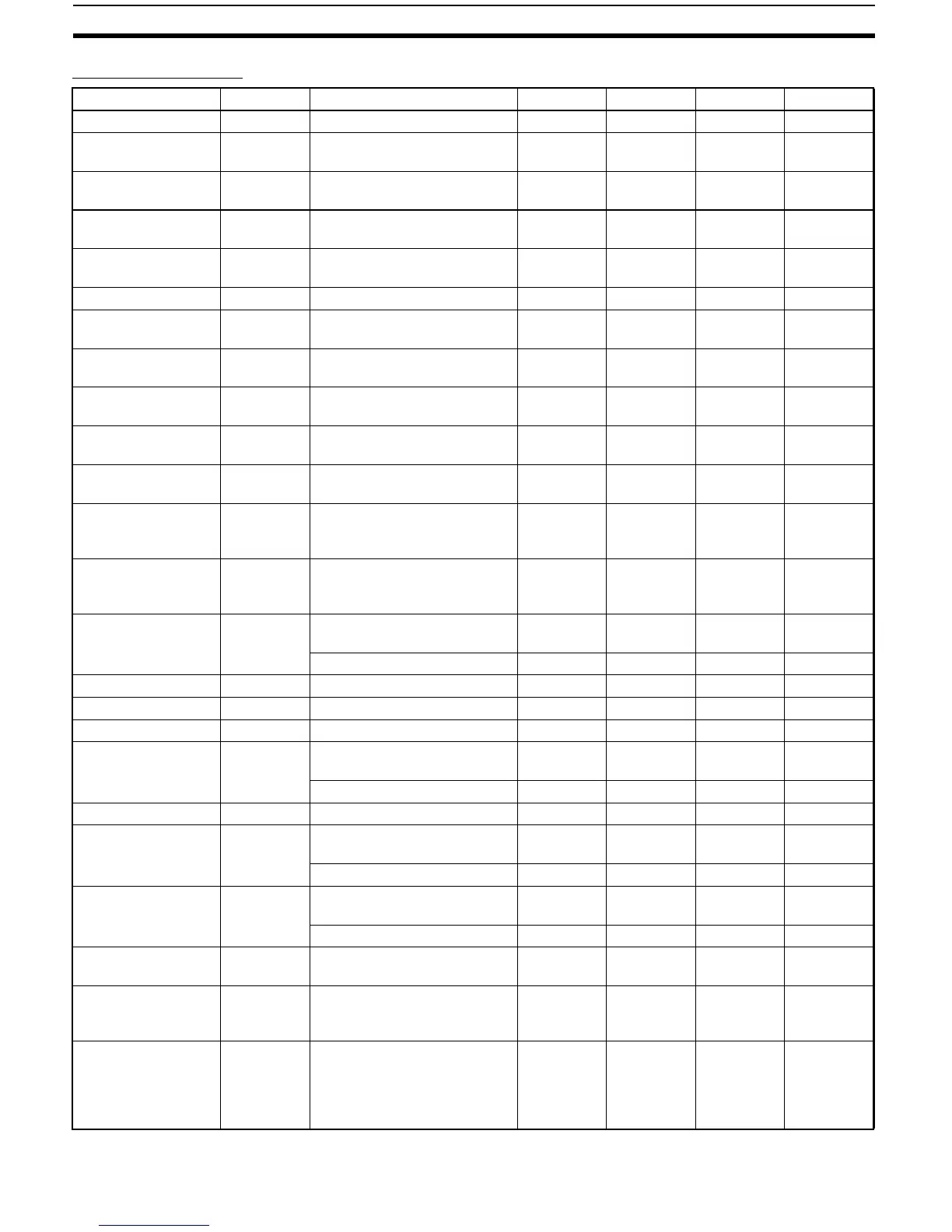
Adjustment Level
Parameters Characters Setting (monitor) value Display Default Unit Set value
AT Execute/Cancel at OFF, ON off, on OFF None
Communications
Writing
cmwt OFF, ON off, on OFF None
Heater Current 1
Value Monitor
ct1 0.0 to 55.0 A
Leakage Current 1
Monitor
lcr1 0.0 to 55.0 A
Heater Burnout
Detection 1
hb1 0.0 to 50.0 0.0 A
HS Alarm 1 hs1 0.0 to 50.0 50.0 A
SP 0 sp-0 SP lower limit to SP upper
limit
0EU
SP 1 sp-1 SP lower limit to SP upper
limit
0EU
SP 2 sp-2 SP lower limit to SP upper
limit
0EU
SP 3 sp-3 SP lower limit to SP upper
limit
0EU
Temperature Input
Shift
ins −199.9 to 999.9 0.0 °C or °F
Upper-Limit Temper-
ature Input Shift
Value
insh −199.9 to 999.9 0.0 °C or °F
Lower-Limit Temper-
ature Input Shift
Value
insl −199.9 to 999.9 0.0 °C or °F
Proportional Band p Universal-input: 0.1 to 999.9 8.0 °C or °F
(See note.)
Analog input: 0.1 to 999.9 10.0 %FS
Integral Time i 0 to 3,999 233 Second
Derivative Time d 0 to 3,999 40 Second
Cooling Coefficient c-sc 0.01 to 99.99 1.00 None
Dead Band c-db Universal-input: −1
99.9 to
999.9
0.0 °C or °F
(See note.)
Analog input: −19.99 to 99.99 0.00 %FS
Manual Reset Value of-r 0.0 to 100.0 50.0 %
Hysteresis (Heating) hys Universal-input: 0.1 to 999.9 1.0 °C or °F
(See note.)
Analog input: 0.01 to 99.99 0.10 %FS
Hysteresis (Cooling) chys Universal-input: 0.1 to 999.9 1.0 °C or °F
(See note.)
Analog input: 0.01 to 99.99 0.10 %FS
SP Ramp Set Value sprt OFF or 1 to 9,999 off, 1 to
9999
OFF EU/s, EU/
min
MV Upper Limit ol-h MV lower limit +0.1 /105.0
(standard)
0.0 to 105.0 (heating/cooling)
105.0 %
MV Lower Limit ol-l −5.0 to MV upper limit −0.1
(standard)
−105.0 to 0.0 (heating/cool-
ing)
−5.0 (stan-
dard)
−105.0
(heating/
cooling)
%
Note Set “none” as the unit for Controllers with Analog Inputs.
 Loading...


