A Appendices
A - 38
E5@C-T Digital Temperature Controllers User’s Manual (H185)
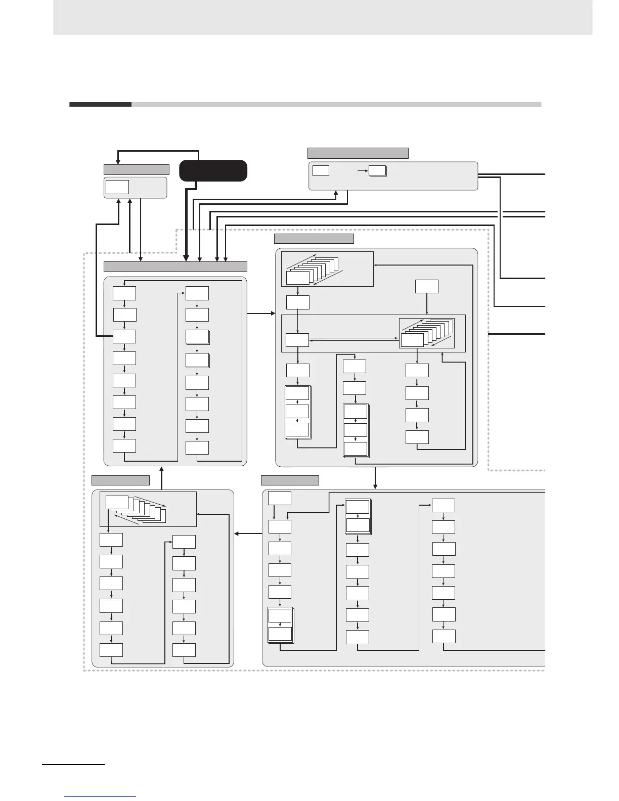
A-9 Parameter Flow
Some parameters may not be displayed depending on the model and other settings.
stb
0.00
psps
0
p
8.0
i
233
wt-b
off
ins
0.0
inrt
1.000
d
40
c-p
8.0
c-i
233
M
c-d
40
l.adj
1234
at
off
cmwt
off
spmd
psp
fsp
0
M
Adjustment Level
Display
Displayed only once
when entering
Adjustment Level.
AT Execute/Cancel
Communications
Writing
SP Mode
Fixed SP
PV Input Shift
PV Input Slope
Coefficient
Wait Band
Standby Time
Program SP Shift Value
Proportional Band
Integral Time
Derivative Time
Proportional Band (Cooling)
Integral Time (Cooling)
Derivative Time (Cooling)
c-db
0.0
Dead Band
ct1
0.0
hb1
0.0
M
Heater Current 1 to 2
Value Monitor
Heater Burnout
Detection 1 to 2
lcr1
0.0
hs1
50.0
M
Leakage Current 1 to 2
Value Monitor
HS Alarm 1 to 2
Adjustment Level
M
M
M
M
M
M
M
M
M
M
M
M
M
M
M
M
M
rpt
0
link
end
M
pid
1
M
PID Set No.
Display Segment Selection
END or 0 to Number of segments used − 1
d.seg
end
U
Display Program
Selection
Press the U Key
for at least 1 s in
Program SP Mode.
Number of
Segments Used
For end
Program
Repetitions
Program
Link
Destination
Process Value/Set
Point 1 or Process
Value/Set Point 2 in
Operation Level
s-no
8
M
7
6
5
4
3
2
1
d.prg
0
D
7
6
5
4
3
2
1
d.seg
0
al1l
0
al-1
0
al1h
0
M
M
Alarm Value
1 to 4
Alarm
Upper Limit
1 to 4
Alarm
Lower Limit
1 to 4
of1
0.00
M
ts1s
0
on1
0.00
M
M
Time Signal 1 to 2
Set Segment
Time Signal 1 to 2
ON Time
Time Signal 1 to 2
OFF Time
25
0
U
D
U
D
Program Setting Level
styp
ramp
Segment n Format
sp
0
Segment n SP
pr
0
Segment n Slope
time
0.00
Segment n Time
M
M
For 0 to 7
M
M
M
M
M
M
M
1.c-d
40
1.cdb
0.0
1.ofr
s0.0
1.olh
100.0
1.oll
0.0
1.aut
1320
1.lba
0
M
1.p
8.0
1.i
233
1.d
40
1.c-p
8.0
1.c-i
233
PID 1
Proportional
Band
PID 1 Integral
Time
PID 1
Derivative Time
PID 1
Proportional
Band (Cooling)
PID 1 Integral
Time (Cooling)
PID 1
Derivative Time
(Cooling)
PID 1 Dead
Band
PID 1 Manual
Reset Value
PID 1 MV Upper
Limit
PID 1 MV Lower
Limit
PID 1 Automatic
Selection Range
Upper Limit
PID 1 LBA
Detection
Time
M
M
PID Setting Level
M
M
M
M
M
M
M
M
M
M
Display PID
Selection
8
7
6
5
4
3
2
d.pid
1
U
D
hold
off
ct1
0.0
pgsg
0.00
prg
0
a-m
lcr1
0.0
o
0.0
c-o
0.0
r-r
rst
25
0
25
0
v-m
0.0
M
seg
0
stbm
0.00
prgt
0.00
rptm
0
Process
Value/Set Point 1
Process
Value/Set Point 2
Auto/Manual Switch
Program No. Monitor/
Segment No. Monitor
Program Number
Hold
Segment Number
Remaining
Standby Time
Monitor
Heater Current 1 to
2 Value Monitor
Leakage Current 1
to 2 Value Monitor
MV Monitor
(Heating)
MV Monitor
(Cooling)
Valve Opening
Monitor
Elapsed
Program Time
Monitor
Program Execution
Repetitions Monitor
Run/Reset
(of the program)
Operation Level
M
M
M
M
M
M
M
M
M
M
M
M
M
M
M
25
50.0
PV/Manual MV
Manual Control Level
Press O Key for
at least 3 s while
a-m is displayed.
Press O or S
Key for at least
1 s.
*1
Press S
Key for at
least 1 s.
*1
S
* The monitor/setting items to display are set in the Monitor/Setting Item 1 to 5 parameters
(Advanced Function Setting Level).
PF Monitor/Setting
Item display 2 to 5
Monitor/Setting Item Level
25
0
PF Monitor/
Setting Item
display 1
Press O Key for less than 1 s.
Press O Key for less than 1 s.
Press S Key.
*2
Press S Key.
*2
Starting in manual mode
Power ON
Press O
Key for
less than
1 s.
Press O
Key for less
than 1 s.

 Loading...