6 - 25
6 Programless Communications
E5C-T Digital Temperature Controllers Programmable Type Communications Manual (H186)
6-4 Connecting to CP-series PLCs
6
6-4-2 Switch Settings and Wiring
Before you attach the CP1W-CIF11 to the CP1E, turn OFF pin 4 on the DIP switch for operation set-
tings on the back of the CP1W-CIF11 and turn ON the rest of the pins.
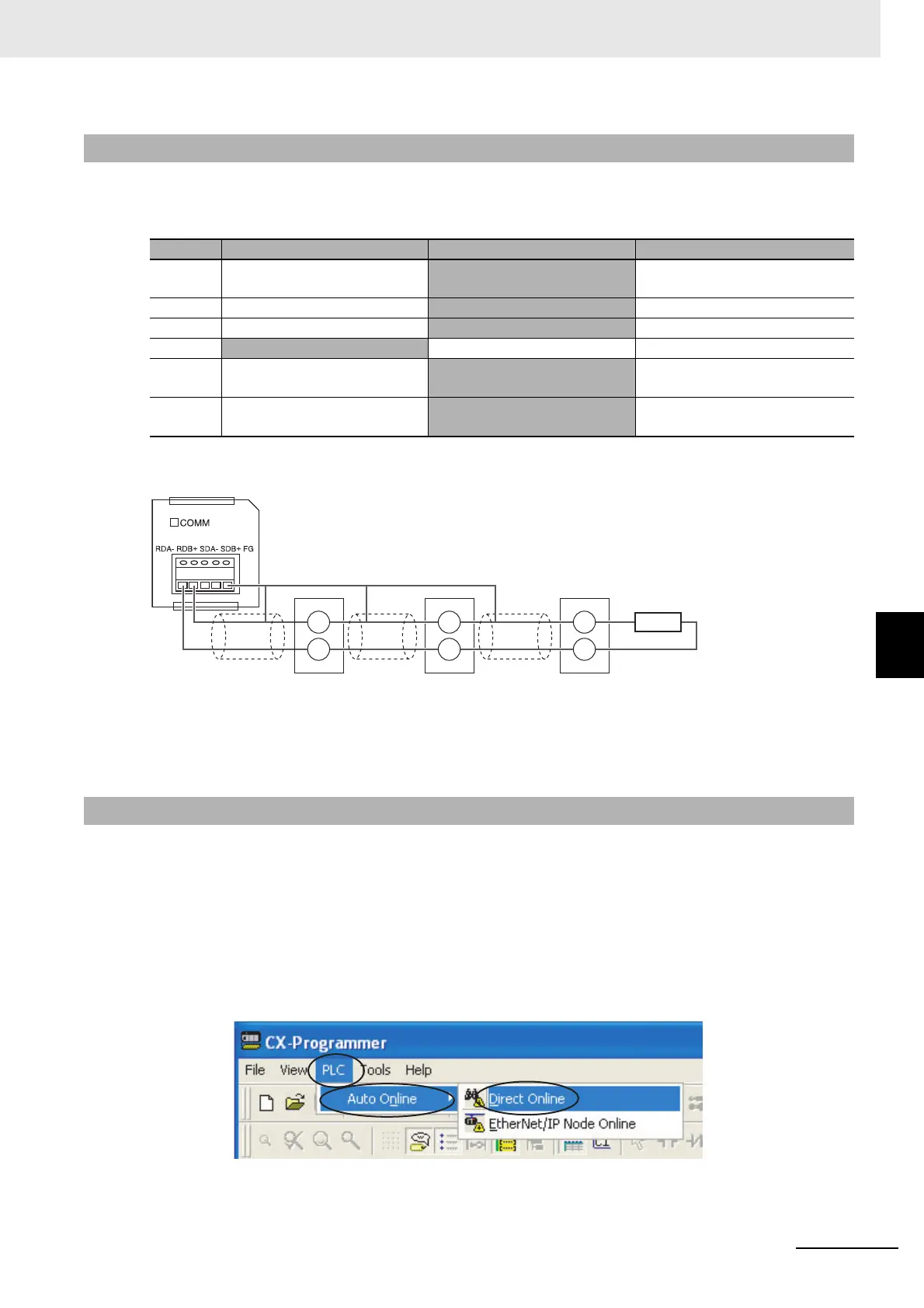
Wire the CP1W-CIF11 to the E5CC-T Controllers as shown below.
Note: 1 The maximum transmission distance is 50 m for the CP1W-CIF11 and 500 m for the CP1W-CIF21.
2 For wiring methods, refer to A-3-2 Recommended RS-422A/485 Wiring in the CP1E CPU Unit Hardware
User’s Manual (Cat. No. W479).
Set up communications on the CP1E to enable communicating with the E5CC-T Controllers.
PLC operation will stop and the power supply will be cycled during the setup procedure. Make sure that
this will not create any problems in the controlled system.
Connecting to the PLC
(1) Connect the computer to the CP1E with a USB cable and then start the
CX-Programmer.
(2) Select PLC
−
Auto Online
−
Direct Online from the menu bar.
6-4-2 Switch Settings and Wiring
Pin OFF ON Setting
1 No terminating resistance
Terminating resistance on both
ends
Terminating resistance selection
2 4-wire
2-wire 2-wire or 4-wire selection
3 4-wire
2-wire Same as above.
4
--- --- Not used.
5 RS control disabled. (Signal
always received.)
RS control enabled. RS control selection for RD
6 RS control disabled. (Signal
always sent.)
RS control enabled. RS control selection for SD
6-4-3 PLC Setup
Shield Shield Shield
13
14
E5CC-T
No.0
E5CC-T
No.1
E5CC-T
No.2
B(+)
A(−)
13
14
B(+)
A(−)
13
14
B(+)
A(−)
CP1W-CIF11
120
Ω (1/2 W)
terminating resistance