6 - 29
6 Programless Communications
E5C-T Digital Temperature Controllers Programmable Type Communications Manual (H186)
6-4 Connecting to CP-series PLCs
6
6-4-4 E5@C-T Controller Setup
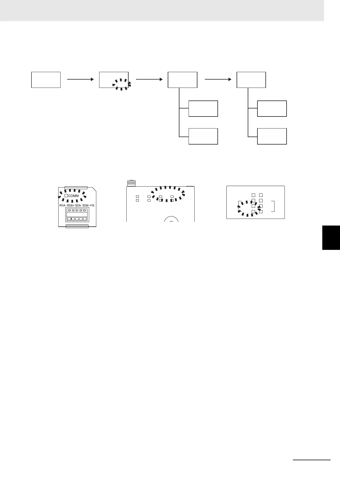
If you are using the CJ1W-SCU21-V1, the SD1 and RD1 indicators will flash. If you are
using the QJ71C24N-R4, the SD and RD indicators for channel 1 (CH1) will flash.
For a Mitsubishi PLC, the ERR. indicator on the Serial Communications Module will light during the
copying process. Ignore it and check the operation. The ERR. indicator will go out when the PLC is
restarted.
Note: Refer to 6-2-9 Copying Parameter Settings for details on the copying operation.
copy
off
copy
all
copy
all
No.0
“ALL” flashes. Copying starts. Copying completed.
No.0
copy
No.1
25
0
No.1
copy
No.2
25
0
No.2
copy
off
No.0 No.0
Wait for 3 s. Copying
processed.
CJ1W-SCU21-V1 QJ71C24N-R4CP1W-CIF11
ERC
RUN
RD2
SCU21-V1
RD1
SD2
RDY
UNIT
ERH
SD1
2
3
4
5
QJ71C24N-R4
CH1
RUN
NEU.
SD
RD
ERR.
NEU.
SD
RD
CH2
Press the
U Key.
copy is displayed on the
No. 1 Controller and then
the No. 2 Controller.
The Controllers are
automatically reset when
copying is completed.