4 Temperature Controllers E5CSV
Operation
E5CSV
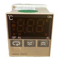
Settings before Turning ON the Power
E5CSV
Remove the E5CSV from the case to make the settings.
1. Insert the tool into the two tool insertion holes (one on the top and
one on the bottom) and release the hooks.
2. Insert the tool in the gap between the front panel and rear case,
and pull out the front panel slightly. Grip the front panel and pull
out fully. Be sure not to impose excessive force on the panel.
3. When inserting the E5CSV, check to make sure that the sealing
rubber is in place and push the E5CSV toward the rear case until
it snaps into position. While pushing the E5CSV into place, push
down on the hooks on the top and bottom surfaces of the rear
case so that the hooks are securely locked in place. Make sure
that electronic components do not come into contact with the
case.
Note: 1. The INIT switch is always OFF during normal operation.
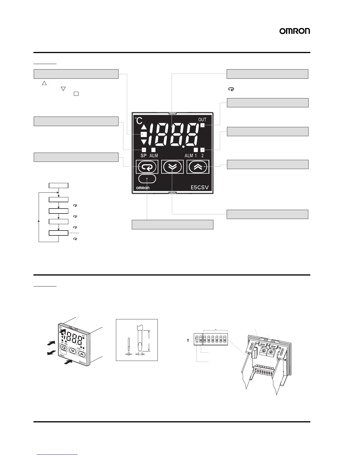
Deviation indicators
The indicator lights when the PV is greater than
the SP and the indicator lights when the PV is
less than the SP. The indicator (green) lights
when the deviation is less than 1% FS (0.25% FS
for multi-input models). These indicators flash
during ST (self-tuning)/AT (auto-tuning).
Mode indicators
The SP indicator lights when the setting
temperature is being displayed. The ALM
indicator lights when the alarm value 1 is
being displayed.
PV, SP, Alarm Value, Input Shift Display
Alarm indicators
ALM1 (Alarm 1): Lights when the alarm 1
output is ON.
ALM2 (Alarm 2): For future use.
Up Key
Pressing the Up Key increases the
SP/alarm value display. Keeping the Up
Key pressed continues to increase the
display value. When the internal protect
switch is ON, press the Up Key while
holding down the Lock Release Key.
Output indicator
Lights when the control output is ON.
The display switches each time the
Key is pressed.
Lock Release Key
When the protect switch is ON, the set
value can be changed by pressing the Up
and Down Keys while holding down the
Lock Release Key.
Down Key
Pressing the Down Key decreases the
SP/alarm value display. Keeping the Down
Key pressed continues to decrease the
display value. When the internal protect
switch is ON, press the Down Key while
holding down the Lock Release Key.
When the power is turned ON, normally the
display will use the display items in the following
order each time the Mode Key is pressed.
Mode Key
PV
SP
Alarm value 1
Input shift value
Power ON
Press the Key.
Press the Key.
Press the Key.
Press the Key.
This item is not displayed when
the Control Mode Switch 4 is OFF.
Flat-blade screwdriver
(Unit: mm)
(1)
(1)
(2)
(3)
Tool insertion hole
0.4 2.0
20 min.
P
ON
X123456
Alarm mode switch (See note 1.)
Temperature range switch
Control mode switches
INIT switch
(See note 2.)
Protect switch
ON