E5jK-T
E5jK-T
21
Precautions when Wiring
Use
ducts to separate input leads and power lines in order to protect the Controller and its lines from external noise.
Solderless terminals are recommended when wiring the Controller
.
Tighten
the terminal screws using a torque no greater than
0.78 N
S
m, or 8 kgf
S
cm max. T
ake care not to tighten the terminal screws too tightly
.
Power
Blocks
The E5AK/E5EK has independent power supplies for each of the terminal blocks shown below
.
10
9
8
7
6
5
4
3
2
1
30
29
28
27
26
25
24
23
22
21
20
19
18
17
16
15
14
13
12
11
31 32
33
AB C
B
FD
C
E
10
9
8
7
6
5
4
3
2
1
20
19
18
17
16
15
14
13
12
11
21 22
23
A B/C C
B
FD
E
E5AK
E5EK
The E5CK has independent power supplies for each
of the terminal blocks shown below
. However
, note
that the power supplies for blocks C (exclude relay
output) and D are shared for the following Option
Unit.
•
Option Unit: E53-CKB or E53-CKF
AC
5
4
3
2
1
10
9
8
7
6
C
DB
11 12
13 14
E5CK
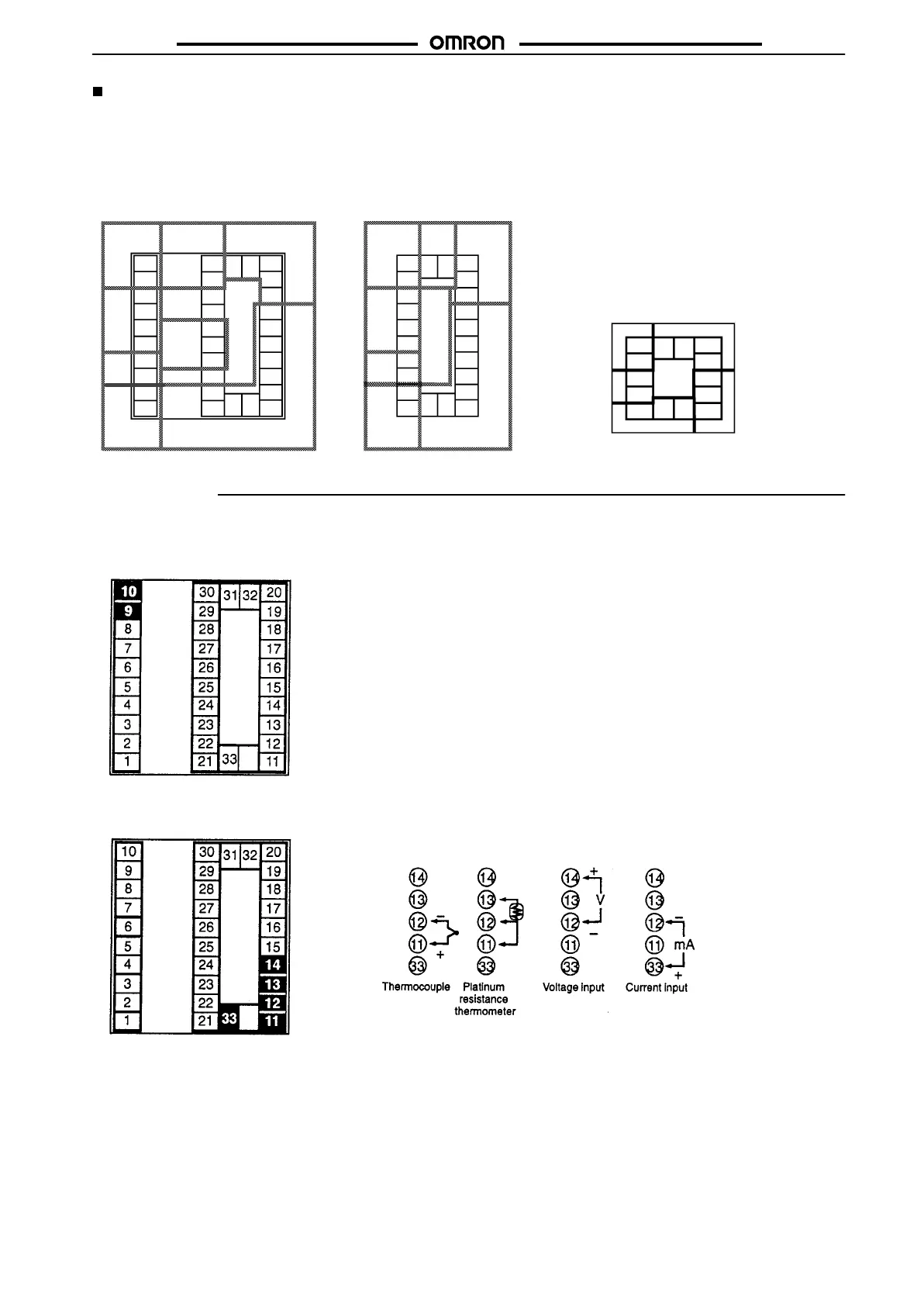
E5AK Wiring
In
the following wiring diagrams, the left side of the terminal numbers indicate the inside of the Controller
.
Power Supply
Input 100 to 240 V
AC or 24 V
AC/DC to terminal numbers 9 and 10 according to the specifications.
Sensor Input
Connect the sensor input to terminal numbers 1
1 to 14 and 33 as follows according to the input type.

 Loading...


