6 Digital Temperature Controllers E5GN
■ Communications Specifications
Note: The baud rate, data bit length, stop bit length, or vertical parity can be individually set using the communications setting level.
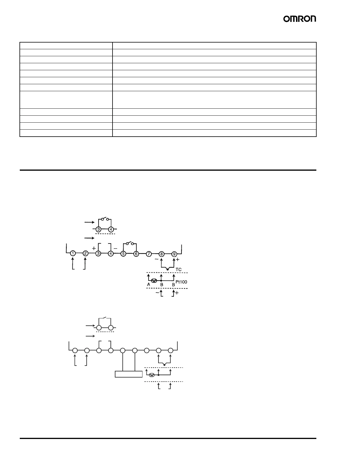
Wiring Terminals
• The voltage output (control output) is not electrically insulated from
the internal circuits. When using a grounding thermocouple, do not
connect the control output terminals to the ground. If the control
output terminals are connected to the ground, errors will occur in
the measured temperature values as a result of leakage current.
• Standard insulation is applied to the power supply I/O sections. If
reinforced insulation is required, connect the input and output ter-
minals to a device without any exposed current-carrying parts or to
a device with standard insulation suitable for the maximum operat-
ing voltage of the power supply I/O section.
Transmission path connection Multiple points
Communications method RS-485 (two-wire, half duplex)
Synchronization method Start-stop synchronization
Baud rate 1,200/2,400/4,800/9,600/19,200 bps
Transmission code ASCII
Data bit length (see note) 7 or 8 bits
Stop bit length (see note) 1 or 2 bits
Error detection Vertical parity (none, even, odd)
Frame check sequence (FCS): with SYSWAY
Block check character (BCC): with CompoWay/F
Flow control Not available
Interface (see note) RS-485
Retry function Not available
Communications buffer 40 bytes
12 VDC
21 mA
Analog input
Input power supply
Relay output
Voltage output
Alarm output/control output 2/input error output
Control output
Two input power supplies are available:
100 to 240 VAC or 24 VAC/VDC (no polarity).
1
9
TC
Pt
A
A
B
B
B
2 3 4
3 4
5 6 7
8
Control output
Relay output
Voltage output
Input power supply
12 VDC
21 mA
Analog input
(+)
(−)
−
−
−
RS-
485
Host
Thermocouple
Infrared temperature senso
Temperature-resistance
thermometer
Two input power supplies are available:
100 to 240 VAC or 24 VAC/VDC (no polarity).
+
+
+
Standard Model
Communication Model