EasyManuals Logo

Omron fh series Construction Guide

Omron fh series
119 pages
To Next Page IconTo Next Page
To Previous Page IconTo Previous Page
Page #27 background imageLoading...
Page #27 background image
23
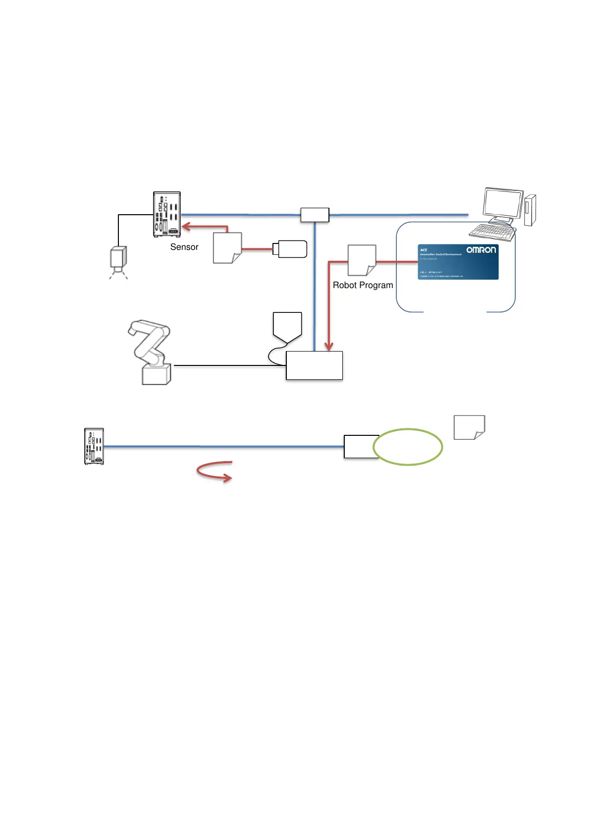
3.2.2. Connecting Vision Sensor and Robot Controller
When following the procedures in Chapter 5, you can complete necessary settings for
communications by loading environment data to the Vision Sensor and robot
programs to the robot controller. Additionally, executing a robot program for startup
establishes TCP/IP connection between the Vision Sensor as a server and the robot
controller as a client.
3.2.3. Setting Vision Sensor
When following the procedures in Chapter 6, you can complete settings for the Vision
Sensor required for application construction, calibration between camera and robot,
and controlling the robot such as driving robot by the Vision Sensor's operation.
Additionally, you can check the setting results of the Vision Sensor by actually moving
the robot.
Robot
Robot controller
Vision Sensor
Environment data
PC software
Robot Program
USB memory
ACE
Switching hub
PC
1) Connection request
3) Response
(Communication start)
2) Response/
Connection
request
Vision Sensor
(TCP server)
Robot controller
(TCP client)
Robot
program
for startup
Execution

Other manuals for Omron fh series

Questions and Answers:

Question and Answer IconNeed help?

Do you have a question about the Omron fh series and is the answer not in the manual?

Omron fh series Specifications

General IconGeneral
TypeMachine Vision System
SeriesFH Series
Power Supply24 VDC
Storage Temperature-20 to 60°C
Humidity35 to 85% RH (non-condensing)
Image SensorCMOS
Processing SpeedHigh-speed processing
ConnectivityEthernet
I/ODigital I/O
Operating SystemEmbedded OS
I/O PortsEthernet, USB

Related product manuals