EasyManuals Logo

Omron fh series Construction Guide

Omron fh series
119 pages
To Next Page IconTo Next Page
To Previous Page IconTo Previous Page
Page #28 background imageLoading...
Page #28 background image
24
3.2.4. Designing Robot Programs
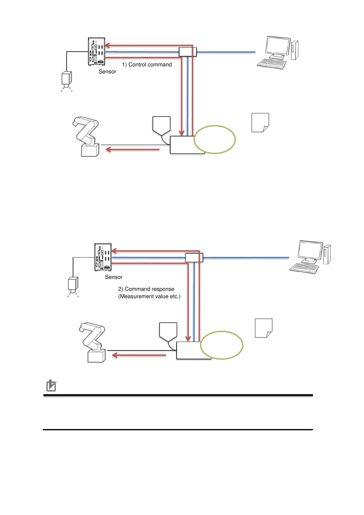
Described in the following figure, when following the procedures in Chapter 7, you can
understand an implementation methodology for robot programs to control the Vision
Sensor such as switching scenes or executing measurements by running robot
programs in the robot controller described in the following figure.
Precautions for Correct Use
The implementation procedures for robot programs noted in Chapter 7 are a
reference. You should design, implement, and test actual operated robot programs
based on the used environment and robot applications.
Robot
Robot controller
Vision Sensor
2) Command execution
(Driving the robot etc.)
1) Control command
3) Command response
(Current position etc.)
Robot program
for startup
Execution
Switching hub
PC
Robot
Robot controller
Vision Sensor
3) Command execution
(Driving the robot etc.)
2) Command response
(Measurement value etc.)
1) Control command
(Measurement etc.)
Sample
Program
Execution
Switching hub
PC

Other manuals for Omron fh series

Questions and Answers:

Question and Answer IconNeed help?

Do you have a question about the Omron fh series and is the answer not in the manual?

Omron fh series Specifications

General IconGeneral
TypeMachine Vision System
SeriesFH Series
Power Supply24 VDC
Storage Temperature-20 to 60°C
Humidity35 to 85% RH (non-condensing)
Image SensorCMOS
Processing SpeedHigh-speed processing
ConnectivityEthernet
I/ODigital I/O
Operating SystemEmbedded OS
I/O PortsEthernet, USB

Related product manuals