EasyManua.ls Logo

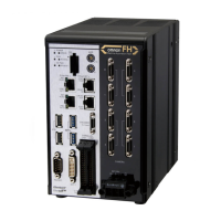
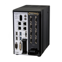
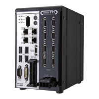
Omron fh series - User Manual

Omron fh series
582 pages
To Next Page IconTo Next Page
Loading...
Vision Sensor
FH/FHV Series
Vision System
Users Manual
FH-1£££/FH-1£££-££
FH-2£££-££/FH-2£££-££
FH-3£££/FH-3£££-££
FH-5£££-££/FH-5£££-££
FH-L£££/FH-L£££-££
FHV7£-£££££-C/FHV7£-£££££-S££/FHV7£-£££££-S££-£
£/FHV7£-£££££-H££/FHV7£-£££££-H££-££
Z365-E1-06

Table of Contents

Other manuals for Omron fh series

Questions and Answers:

Omron fh series Specifications

General IconGeneral
TypeMachine Vision System
SeriesFH Series
Power Supply24 VDC
Storage Temperature-20 to 60°C
Humidity35 to 85% RH (non-condensing)
Image SensorCMOS
Processing SpeedHigh-speed processing
ConnectivityEthernet
I/ODigital I/O
Operating SystemEmbedded OS
I/O PortsEthernet, USB

Summary

Relevant Manuals

Special Information

Precautions for Safe Use

Precautions on what to do and what not to do to ensure safe usage of the product.

Precautions for Correct Use

Precautions on what to do and what not to do to ensure proper operation and performance.

Safety Precautions

Safety Symbols and Meanings

Explains the notation used for safety precautions, including WARNING and Caution.

Alert Symbol Meanings

Defines alert symbols like General Prohibition, General Caution, Electrical Hazard, and Explosion Hazard.

Precautions for Safe Use

OMRON Product Fitness Conditions

Specifies conditions and applications where Omron products should not be used, including safety-critical and high-reliability applications.

Power Supply and Wiring (FH Series)

Details power supply voltage, wiring, and confirmation steps for FH series product safety.

Power Supply and Wiring (FHV Series)

Details power supply voltage, polarity, surge protection, and wiring precautions for FHV series.

Precautions for Correct Use

Maintenance (FH Series)

Details maintenance procedures for FH series, including power off, cleaning, and safe access.

Maintenance (FHV Series)

Details maintenance procedures for FHV series, including power off, connector handling, and disposal.

Failsafe Measures

Emphasizes the need for fail-safe measures when controlling stages and robots using measurement results.

Related Manuals

Sections in This Manual

Section 3 Basic Operations

Covers test methods, checking correct measurement, and useful operational functions.

Section 4 Setting the Controller

Details settings related to the system environment for the controller.

Section 5 Creating Measurement Scenes

Explains methods for saving and loading settings and image data.

Section 6 Performing Measurement and Adjustment

Describes settings related to the system environment for the controller.

Section 8 Setting Windows

Describes window settings, layout arrangement, and custom dialog functions.

Section 9 SavingLoading Data

Explains procedures for saving and loading setting data and image data.

Section 10 Advanced Usage

Covers using user accounts, macros, remote operation, and multi-trigger imaging.

Related product manuals