Item Description
OR The selected figure is displayed with a dotted line in an OK color.
When drawing multiple figures, the entire area is registered as one re-
gion.
NOT The selected figure is displayed with a dotted line in an NG color.
The area outside of the NOT image is registered as a region.
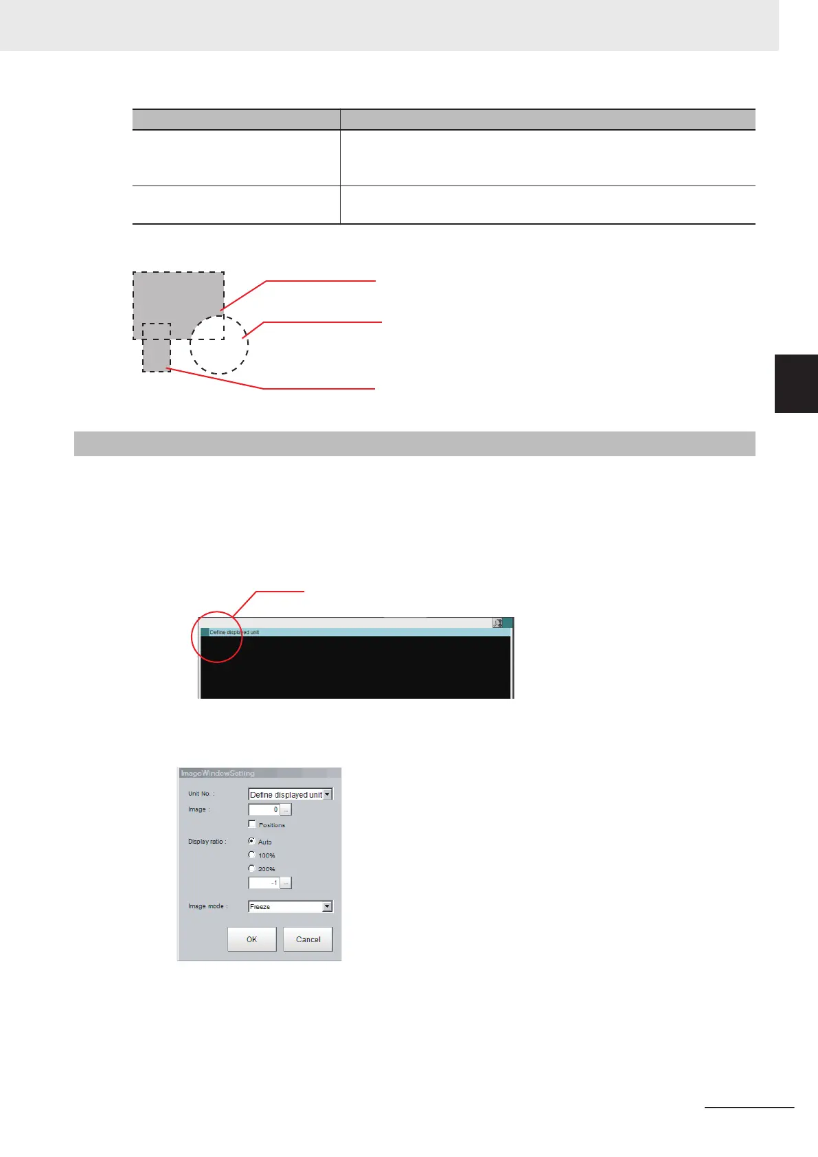
Example: The grey parts are measurement regions.
Image 1 (drawn by OR)
Image 2 (drawn by NOT)
Image 3 (drawn by OR)
3-2-7
Changing the Image Mode and Other Display Contents
The display contents of the Image Pane can be changed in order to make the measurement status
easier to understand.
1 Click the upper left corner of the Image Pane that for which to change to display the settings
dialog box for the Image Pane.
2
The settings dialog box for the Image Pane is displayed. Set the items.
3 Basic Operations
3 - 21
FH/FHV Series Vision System User’s Manual (Z365-E1)
3-2 Basic Knowledge about Operations
3
3-2-7 Changing the Image Mode and Other Display Contents

 Loading...


