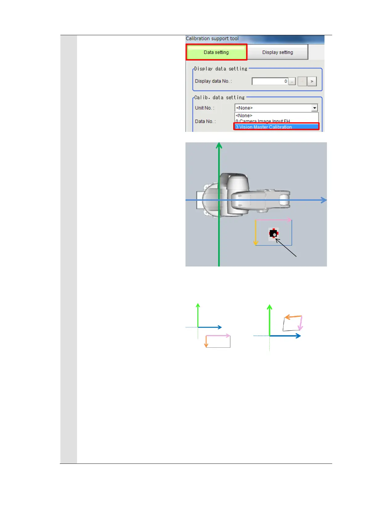
In the [Data setting] tab, set
the unit No. to the “3. Vision
Master Calibration” to check the
relationship between the
camera and robot coordinate
systems got from the
calibration.
* Regarding the robot base
coordinate system shown on
the right figure, set the
“Rotation” at the “Standard
axis” on the “Display setting”
tab in the “Calibration support
tool” to “Anticlockwise”.
If the relation such as directions
and camera coordinate origin
position between the camera
and the robot base coordinate
systems is the same as the
actual system configuration,
the calibration has succeeded.
* Like the NG example, if the
relation between the camera
and the robot base coordinate
systems is different, the
calibration has failed. Review
the camera settings, model
registration, and environment
of lightings and then execute
the calibration again.

 Loading...


