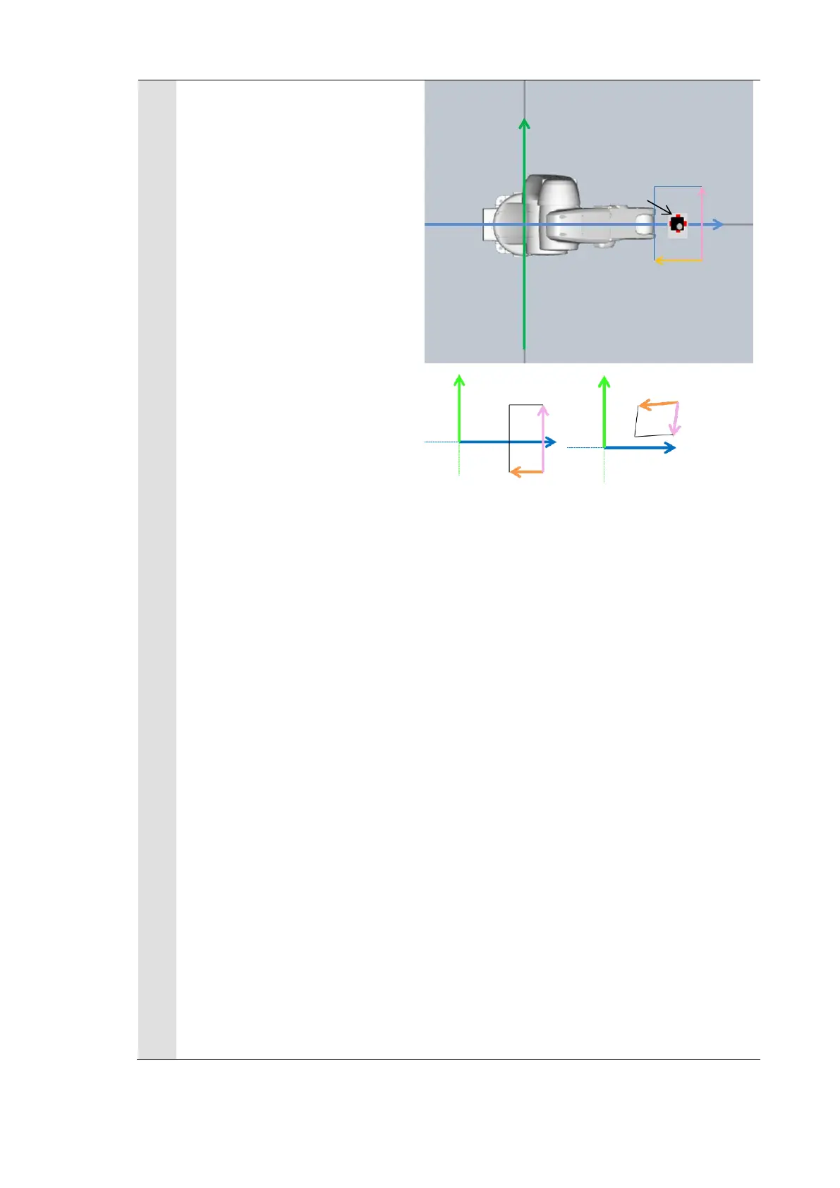
* Regarding the robot base
coordinate system shown on
the right figure, set the
“Rotation” at the “Standard
axis” on the “Display setting”
tab in the “Calibration support
tool” to “Anticlockwise”.
If the relation such as directions
and camera coordinate origin
position between the camera
and the robot base coordinate
systems is the same as the
actual system configuration,
the calibration has succeeded.
* Like the NG example, if the
relation between the camera
and the robot base coordinate
systems is different, the
calibration has failed. Review
the camera settings, model
registration, and environment
of lightings and then execute
the calibration again.
* When using the FHV Series
Smart Camera Vision Sensor,
you can use the Simulation
Software to load a settings data
file that has been saved for
backup. This will allow you to
launch the "Calibration Support
Tool" from the "Tool" menu. For
additional information on
backing up settings data,
please refer to Section 6.5

 Loading...


