* When using the FHV Series
Smart Camera Vision Sensor,
delete the "0. Camera Image
Input FH" unit and in its place
set "Camera Image Input FHV"
as Unit 0.
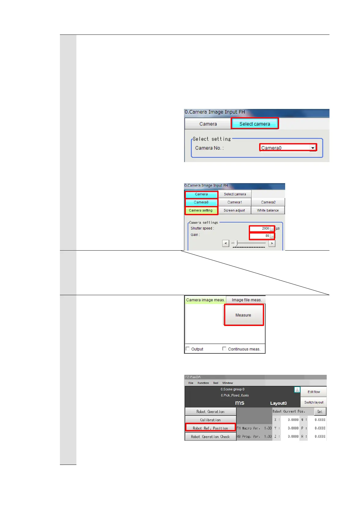
Check the set “Camera No.” by
clicking [Select camera] tab.
* Change the camera number
based on the actual
environment.
Select the set camera number
tab on the “Camera” tab.
Adjust the shutter speed and
gain of the camera on the
“Camera settings” area.
Register a workpiece as a
model for Grip Correction by
operations as same as those at
step 5 in Chapter 6.3.1.
Select [Camera image meas.]
on the Main Window of the
Vision Sensor and detect a
workpiece position for Grip
Correction with clicking
[Measure].
Click [Robot Ref. Position] on
the Main Window of the Vision
Sensor to open the “Robot Ref.
Position” dialog.

 Loading...


