H5RA
H5RA
277
DescriptionFunctionName
Normally
read in
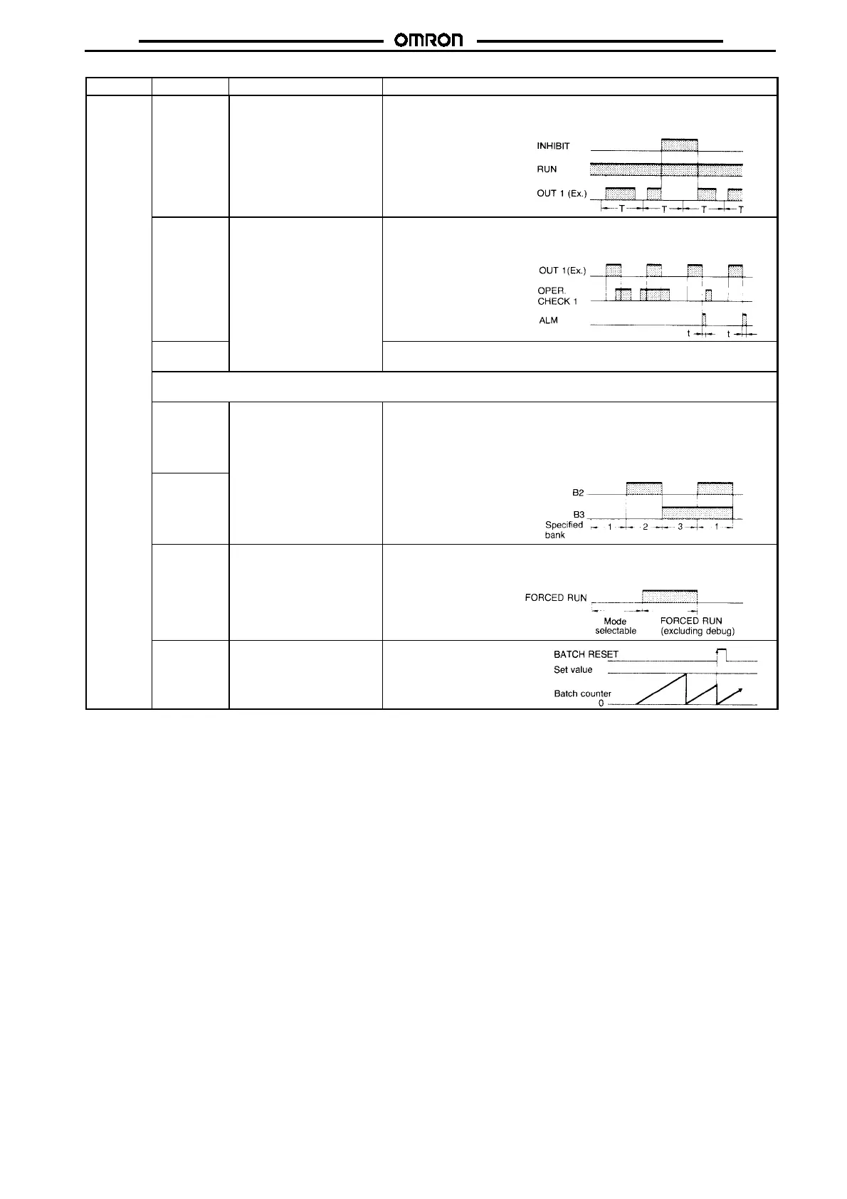
INHIBIT Turns OFF all the control
outputs.
The timer turns OFF all the control output signals at the leading edge of this
input signal. The output signals remain OFF as long as this signal is ON.
The timer can continue the timing even while the outputs are turned OFF.
OPER.
CHECK 1
Checks whether the
actuator is operating
normally.
If this input signal does not turn ON while control output 1 is turned ON, the
timer produces an alarm output signal when control output 1 is turned OFF.
For one-shot time t, refer to the description of the alarm output.
OPER.
CHECK 2
If this input signal does not turn OFF while control output 2 is turned ON, the
timer produces an alarm output signal when control output 2 is turned OFF.
Note: Both input signals OPER. CHECK 1 and 2 share the same alarm output. Therefore, whether the alarm output has
been activated.
B2 (Bank 2)
Specifies one of three
memory blocks (banks).
A program can be stored in each bank and the program to be executed
specified by either or both of these input signals. The program at the
specified bank can be changed or executed. Banks 2 and 3 are selected by
the corresponding input signal. When the B2 and B3 signals are both OFF
or when they are both ON at the same time, bank 1 is selected. Bank
B3 (Bank 3)
selection can be done in the PROG mode or in the RUN mode only when
the timer is not timing.
FORCED
RUN
Forcibly sets the RUN mode
to protect the program from
damage or loss.
When this input signal is turned ON, the RUN mode is set irrespective of the
position of the RUN/PROG selector switch on the front panel. Only when it
is turned OFF can the PROG mode and DEBUG mode be specified.
BATCH
RESET
Resets the present count
value of a batch counter.
The batch counter of the
specified bank is reset at the
leading edge of this input
signal.
Note: 1. These signals are only acknowledged on power application.
2. In the timing charts in the above tables, T denotes the cycle time.
3. Of the input signal pulses in the figures in the above tables, the shaded pulses indicate that the input signal is level-sensitive. The
pluses not shaded but with up and down arrows indicate that the input signal is edge-sensitive.
 Loading...


