28 Multifunction Digital Timer H5CX-A/-L (Twin Timer Function)
Explanation of Functions
OFF Time Range (oftr) (Setting possible using DIP
switch.)
Set the time range for the OFF time in the range 0.000 s to 9,999 h.
Only settings of type --.-- s (99.99 s), ---.- s (999.9 s), ---- s (9,999 s),
and -- min -- s (99 min 59 s), however, can be made with the DIP
switch. Use the operation keys if another type of setting is required.
ON Time Range (ontr) (Setting possible using DIP
switch.)
Set the time range for the ON time in the range 0.001 s to 9,999 h.
Only settings of type --.-- s (99.99 s), ---.- s (999.9 s), ---- s (9,999 s),
and -- min -- s (99 min 59 s), however, can be made with the DIP
switch. Use the operation keys if another type of setting is required.
Timer Mode (timm) (Setting possible using DIP switch.)
Set either UP (incremental) or DOWN (decremental) timer mode. In
UP mode, the elapsed time is displayed, and in DOWN mode, the
remaining time is displayed.
ON/OFF Start Mode (totm) (Setting possible using DIP
switch.)
Set the output mode. Set either flicker OFF start or flicker ON start.
(For details on output mode operation, refer to “Timing Charts” on
page 30.)
Input Signal Width (iflt) (Setting possible using DIP
switch.)
Set the minimum signal input width (20 ms or 1 ms) for signal, reset,
and gate inputs. The same setting is used for all external inputs (sig-
nal, reset, and gate inputs). If contacts are used for the input signal,
set the input signal width to 20 ms. Processing to eliminate chatter-
ing is performed for this setting.
NPN/PNP Input Mode (imod)
Select either NPN input (no-voltage input) or PNP input (voltage
input) as the input format. The same setting is used for all external
inputs. For details on input connections, refer to “Input Connections”
on page 9.
Display Color (colr)
Set the color used for the present value.
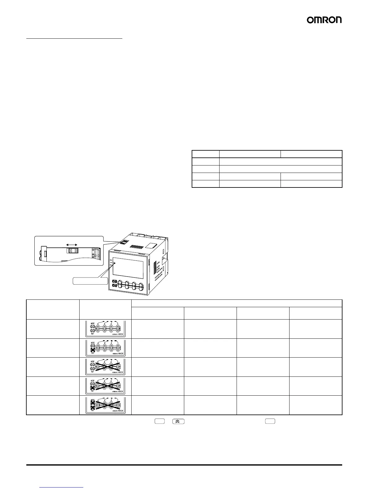
Key Protect Level (kypt)
Set the key protect level.
When the key-protect switch is set to ON, it is possible to prevent setting errors by prohibiting the use of certain operation keys by specifying the
key protect level (KP-1 to KP-5). The key protect indicator is lit while the key-protect switch is set to ON.
Note:Changing mode to timer/twin timer selection mode ( + 1 s min.) or function setting mode ( 3 s min.).
Output OFF Output ON
red Red (fixed)
grn Green (fixed)
r-g Red Green
g-r Green Red
ON
OFF
(See note)
Note: Factory-set to OFF
Key protect indicator
Level Meaning Details
Changing mode
(See note.)
Switching display
during operation
Reset key Up/down key
KP-1
(default setting)
N o Ye s Ye s Ye s
KP-2 No Yes No Yes
KP-3 No Yes Yes No
KP-4 No Yes No No
KP-5 No No No No
MODE
1
MODE