30 Multifunction Digital Timer H5CX-A/-L (Twin Timer Function)
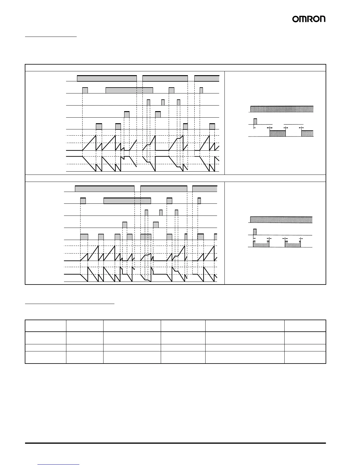
Timing Charts
Twin Timer Operation
The gate input is not included in the H5CX-L8@ models.
Self-diagnostic Function
The following displays will appear if an error occurs.
Note:This includes times when the life of the EEPROM has expired.
Output mode toff: Flicker OFF start
Output mode ton: Flicker ON start
Main display Sub-display Error Output status Correction method Set value after
reset
e1 Not lit CPU OFF Either press the reset key or reset the
power supply.
No change
e2 Not lit Memory error (RAM) OFF Reset the power supply. No change
e2 sum Memory error (EEP)
(See note)
OFF Reset to the factory settings using
the reset key.
0
0
0
UP
DOWN
Power
Start signal
Gate
Reset
Control output
OFF time
ON time
OFF time
ON time
Sustained
Output
Timing
diagram
**
Basic Operation
Power
Output
Timing starts when the start signal goes ON.
The status of the control output is reversed when time
is up (OFF at start).
While the start signal is ON, the timer starts when the
power comes ON or when the reset input goes OFF.
Start signal
input
Timing
OFF
Timing
ON
Timing
ON
Timing
OFF
*
Normal output operation will not be possible if the
ON/OFF set time is too short.
Set the value to at least 100 ms (contact output
type).
**
Start signal input is disabled during timing.
0
0
UP
DOWN
Power
Start signal
Gate
Reset
Control output
OFF time
ON time
OFF time
ON time
Sustained
Output
Timing
diagram
**
Basic Operation
Power
Output
Timing starts when the start signal goes ON.
The status of the control output is reversed when time
is up (ON at start).
While the start signal is ON, the timer starts when the
power comes ON or when the reset input goes OFF.
Start signal
input
Timing
ON
Timing
ON
Timing
OFF
Timing
OFF
*
Normal output operation will not be possible if the
ON/OFF set time is too short.
Set the value to at least 100 ms (contact output
type).
**
Start signal input is disabled during timing.