30
H7BX
• Peak/bottom Hold Enabled (dhld)
This function records the peak and bottom (i.e., minimum) after
counting starts (after turning ON the power supply or changing the
configuration selection mode or function setting). The peak value is
also held when the power supply is interrupted.
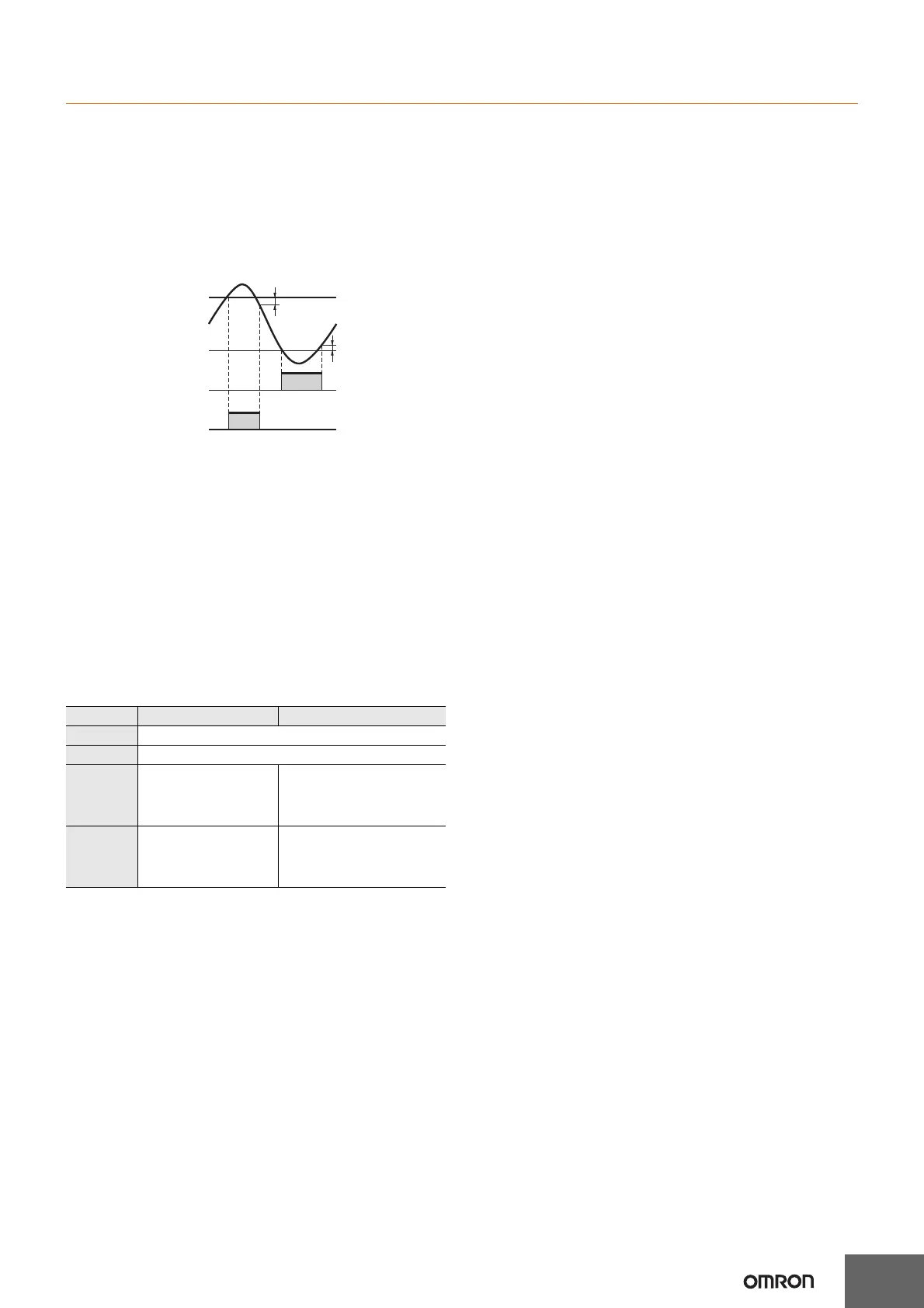
• Output Hysteresis (hys)
This setting can be used to prevent output chattering if the
measurement value fluctuates slightly near the set value.
The measurement value after prescaling is set.
• Output OFF Delay (offd)
This function delays the timing for turning OFF comparative output by
a certain time.
The ON time can be held for the set time if the comparative result
changes in a short time.
Operation will continue and outputs will not change when holding the
value.
• Set Value Upper Limit (sl-h)
Set the upper limit for the set value when it is set in run mode. The
limit can be set to between 1 and 999999.
• Display Color (colr)
Set the color used for the measurement value.
*1. If the tachometer output mode is set to AREA, however, the
measured value is displayed in red when control output 1 is OFF
and in green when control output 1 is ON.
*2. If the tachometer output mode is set to AREA, however, the
measured value is displayed in green when control output 1 is OFF
and in red when control output 1 is ON.
•
Output Allocation (Settings applicable to only H7BX-AW)
(
otst
)
Set the allocation of outputs 1 and 2 (OUT1 and OUT2). If output
allocation is OFF, output 1 (OUT1) is allocated to terminals (5)-(6),
(14)-(17), and output 2 (OUT2) is allocated to terminals (3)-(4), (14)-
(18). If output allocation is ON, output 1 (OUT1) is allocated to
terminals (3)-(4), (14)-(18), and output 2 (OUT2) is allocated to
terminals (5)-(6), (14)-(17).
• Key Protect Level (kypt)
Set the key protect level.
For details, refer to Key Protect Level on page 34.
• Output inversion (ot1i, ot2i)
Set logical inversion of output ON/OFF. In the case of two outputs, it
is possible to individually set output inversion for each of output 1 and
output 2 (OUT1 and OUT2). If output inversion is n-o (Normally
Open), the output turns ON when the set value is reached. If output
inversion is n-c (Normally close), the output turns OFF when the set
value is reached.
• Pulse Cycle Measurement/Pulse Width Measurement
(calm)
Set the measurement mode to pulse cycle measurement or pulse
width measurement.
With pulse cycle measurement, the number of pulse cycles that occur
in 1 s is measured.
With pulse width measurement, the ON time for one pulse is
measured.
An input OFF period of at least 20 ms is required for pulse width
measurement.
If there is no input pulse during pulse width measurement, the
previously measured value will be held.
• Display Unit (unit)
When pulse cycle measurement is used, set the display unit to Hz
(hertz) or s (seconds).
• Counting Interval (intv)
If the measurement speed is 10 kHz when pulse cycle measurement
is used, set the measurement interval to 200 ms or Cont (10 ms min.).
• ON Count Alarm Set Values for Outputs 1 and 2 (OUT1
and OUT2) (on1a and on2a)
The output ON count for notifying the replacement time can be set.
For details, refer to page 35.
• ON Count Monitor Values for Outputs 1 and 2 (OUT1
and OUT2) (on1c and on2c)
The monitor value for output 1 and 2 (OUT1 and OUT2) is only
displayed. It cannot be set.
The output ON count will be 1,000 times the displayed value.
• Cumulative Run Time Alarm Set Value (ot-a)
The cumulative run time for notifying the replacement time can be set.
For details, refer to page 35.
• Cumulative Run Time Monitor (ot-c)
The cumulative run time is displayed. It is not a setting item. The
numerical values are displayed in increments of 0.1 years.
Control output OFF Control output ON
red Red (fixed)
grn Green (fixed)
r-g
*1
Measured value
displayed in red when
both control outputs 1
and 2 are OFF.
Measured value displayed in
green when either control
output 1 or control output 2 is
ON.
g-r
*2
Measured value
displayed in green when
both control outputs 1
and 2 are OFF.
Measured value displayed in
red when either control
output 1 or control output 2 is
ON.
OUTX1
OUTY2
Display value
Comparison value 2
Hysteresis
Hysteresis
Comparison value 1
Set the hysteresis for when
the output turns OFF.