H7CR
H7CR
20
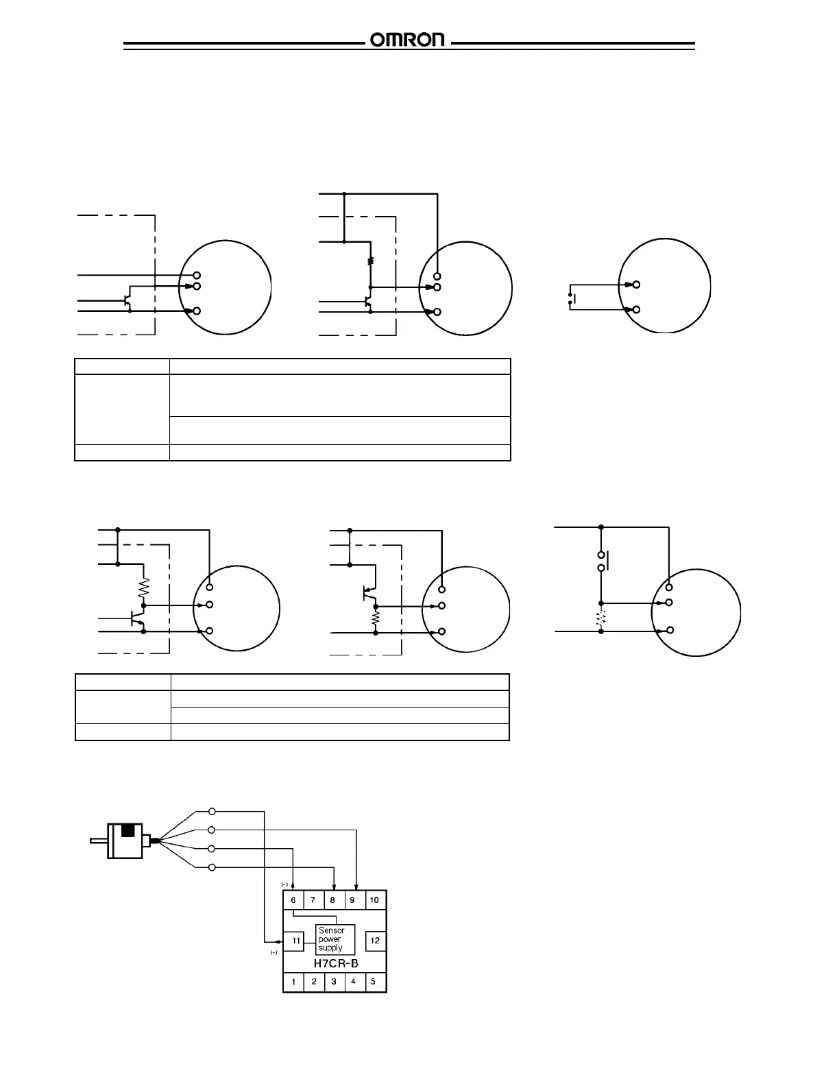
■ CONNECTIONS
The inputs of the H7CR are non-voltage (short circuit or open) inputs and voltage inputs. (Non-voltage inputs only H7CR-S, -8 and -11.)
Sensor
CP1, CP2
(reset), etc.
Input use 0 V
Counter
12 or 24 VDC
Input signal Ratings
Non-contact input High level when transistor is ON
Residual voltage: 2 V max.
Impedance when ON: 1 kΩ max.
Low level when transistor is OFF
Impedance when OFF: 100 kΩ max.
Contact input Use contacts capable of switching 2 mA at 5 VDC
Non-voltage inputs
Solid-State Input (NPN transistor)
Voltage inputs
Solid-State Input (NPN output sensor
powered by built-in DC power source)
Counter
Sensor
CP1, CP2
(reset), etc.
Input use 0 V
12 or 24 VDC
+V
(30 V max.)
0 V
Contact Input
Switch
contact
Counter
CP1, CP2
(reset), etc.
Input use 0 V
Solid-State Input (NPN transistor) Solid-State Input (PNP transistor)
Contact Input
12 or 24 VDC
CP1, CP2
(reset), etc.
Input use 0 V
0 V
Counter
12 or 24 VDC
CP1, CP2
(reset), etc.
Input use 0 V
+V
(30 V max.)
0 V
Counter
Switch
contact
0 V
+V
(30 V max.)
CP1, CP2
(reset), etc.
12 or 24 VDC
Input use 0 V
Input signal Ratings
Voltage input High level when transistor is ON: 4.5 to 30 VDC
Low level when transistor is OFF: 0 to 2 VDC
Contact input Use contacts capable of switching 2 mA at 5 VDC
Sensor
Sensor
+V
(30 V max.)
Rotary encoder input
Counter
Power supply
A phase
B phase
0 V

 Loading...


