15
H7CX (Counter Function)H7CX (Counter Function)
■ Explanation of Functions
Input Mode (
"-3,
) (Setting possible using DIP switch.)
Set increment mode (UP), decrement mode (DOWN), or one of
the increment/decrement modes (UP/DOWN A, UP/DOWN B, or
UP/DOWN C) as the input mode. Input modes other than UP or
DOWN modes cannot be set using the DIP switch and so use the
operation keys if other modes are required. (For details on the
operation of the input modes, refer to Input Modes and Present
Value on page 18.)
Dual Count Calculating Mode (
" +,
)
When using as a dual counter, select either ADD (addition) or
SUB (subtraction) as the calculation method for the dual count
value.
ADD: Dual count value = CP1 PV + CP2 PV
SUB: Dual count value = CP1 PV
-
CP2 PV
Output Mode (
.43,
) (Setting possible using DIP switch.)
Set the way that control output for the present value is output. The
possible settings are N, F, C, R, K-1, P, Q, A, K-2, D, L, and H.
Output modes other than N, F, C, or K-1 cannot be set using the
DIP switch and so use the operation keys if other modes are
required. The output modes that can be set vary with the model.
(For details on the operation of the output modes, refer to Input/
Output Mode Settings on page 19.)
One-shot Output Time (
.3(,
) (Setting possible using DIP
switch.)
Set the one-shot output time (0.01 to 99.99 s) for control output.
One-shot output can be used only when C, R, K-1, P, Q, A, or K-2
is selected as the output mode. Output times other than 0.5 s or
0.05 s cannot be set with the DIP switch and so use the operation
keys if other settings are required.
One-shot Output 2 Time (
.3,
) (Setting possible using DIP
switch.)
When using as a 2-stage counter or batch counter, set the one-
shot output time (0.01 to 99.99 s) for control output (OUT2). One-
shot output can be used only when C, R, K-1, P, Q, A, or K-2 is
selected as the output mode. Output times other than 0.5 s or
0.05 s cannot be set with the DIP switch and so use the operation
keys if other settings are required.
One-shot Output 1 Time (
.3,
)
When using as a 2-stage counter, set the one-shot output time
(0.01 to 99.99 s) for control output (OUT1). One-shot output can
be used only when D, L, or H is selected as the output mode. If
the output time is set to 0.00,
'.+#
is displayed, and outputs are
held. HOLD cannot be set when the output mode is K-2.
Counting Speed (
"-32
) (Setting possible using DIP switch.)
Set the maximum counting speed (30 Hz/5 kHz) for CP1 and CP2
inputs together. If contacts are used for input signals, set the
counting speed to 30 Hz. Processing to eliminate chattering is
performed for this setting.
Reset Input Signal Width (
(%+3
) (Setting possible using DIP
switch.)
Set the reset input signal width (20 ms/1 ms) for reset/reset 1 and
total reset/reset 2 inputs together. If contacts are used for input
signals, set the counting speed to 20 ms. Processing to eliminate
chattering is performed for this setting.
Decimal Point Position (
#/
)
Decide the decimal point position for the present value, CP1/CP2
present values, set value (SV1, SV2), total count value, and dual
count set value.
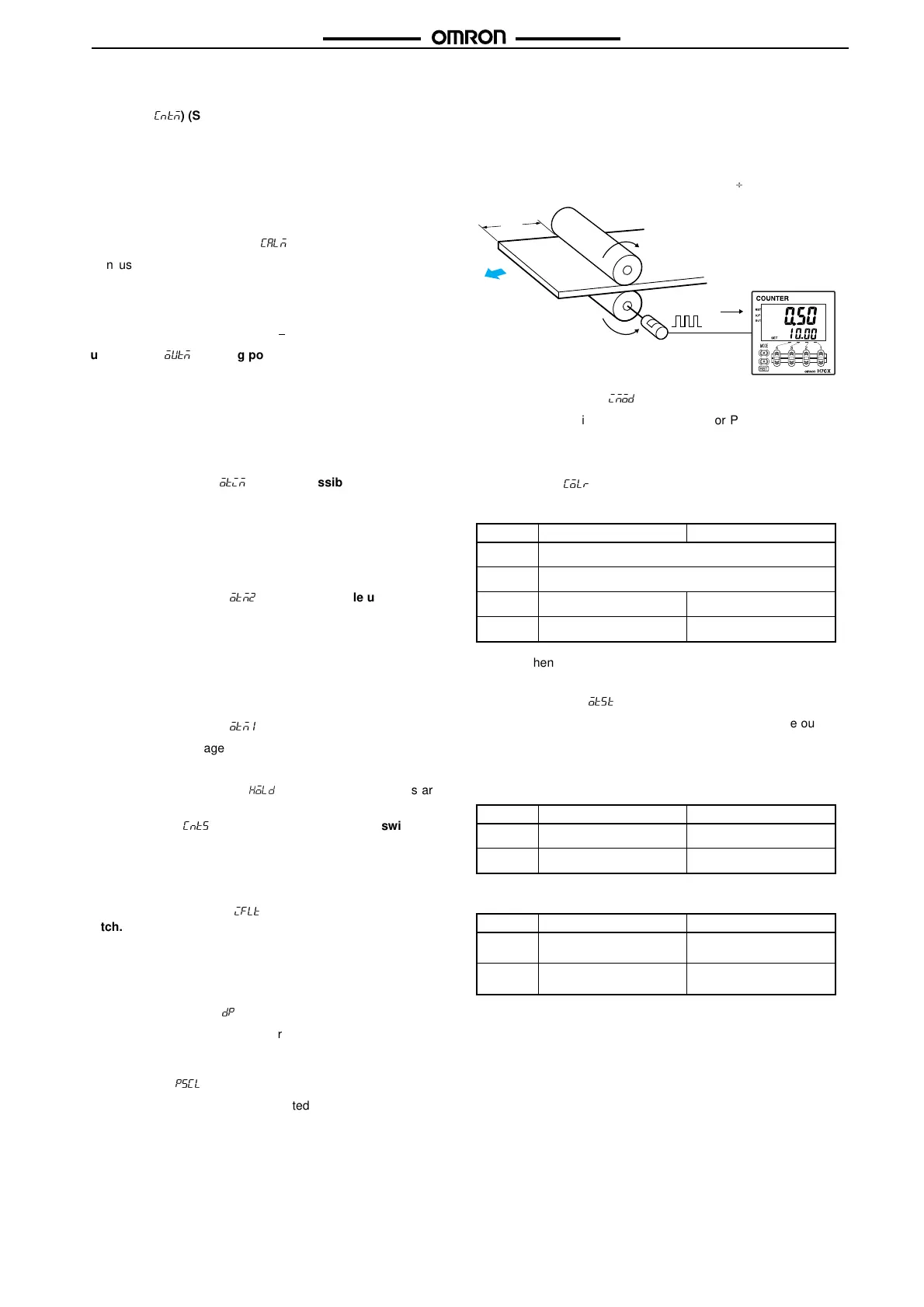
Prescale Value (
/2"+
)
Pulses input to the counter are converted according to the speci-
fied prescale value. (Setting range: 0.001 to 99.999 for 6-digit
models and 0.001 to 9.999 for 4-digit models.)
Example: To display the feed distance for systems that output
25 pulses for a feed length of 0.5 m in the form
@@.@@ m:
1. Set the decimal point position to 2 decimal places.
2. Set the prescale value to 0.02 (0.5
25).
NPN/PNP Input Mode (
(,.#
)
Select either NPN input (no-voltage input) or PNP input (voltage
input) as the input format. The same setting is used for all exter-
nal inputs. For details on input connections, refer to Input Connec-
tion on page 36.
Display Color (
".+1
)
Set the color used for the present value.
Note: When using as a 2-stage counter, this is the status of out-
put 2.
Output Allocation (
.323
)
When using H7CX-AU@ models as a 2-stage counter, the output
can be flexibly allocated to either stage 1 or 2.
Transistor output can be allocated to SV1 and contact output for
SV2 or vice verce, as in the following table.
H7CX-AU/-AUD1
H7CX-AUSD1
Output OFF (See note.) Output ON (See note.)
1$#
Red (fixed)
&1-
Green (fixed)
1&
Red Green
&1
Green Red
OUT1 OUT2
.%%
Transistor (12-13) Contact (3, 4, 5)
.-
Contact (3, 4, 5) Transistor (12-13)
OUT1 OUT2
.%%
Transistor (12-13) Transistor with diode
(3, 4, 5)
.-
Transistor with diode
(3, 4, 5)
Transistor (12-13)
0.5m
Encoder
25 pulses

 Loading...


