2 Digital Indicators K3HB Series (Analog Input Series)
Features
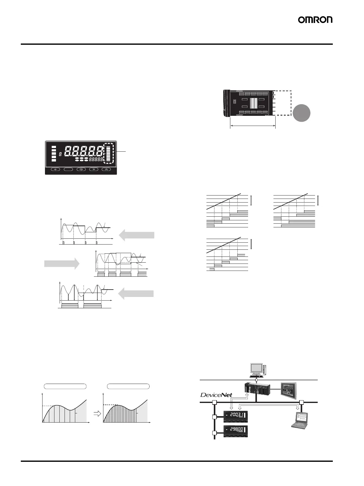
Red-Green Display Allows Easy Recognition
of Judgment Results
• The measurement value display can be set to switch be-
tween red and green in accordance with the status of com-
parative outputs. This means that the status can be
ascertained at a distance.
Position Meter Enables Easy Monitoring of
Operating Status Trends
• The present value with respect to the measurement or dis-
play range (full scale) can be viewed on a bar display. The
operating status can be grasped intuitively, allowing easy
judgement of levels and threshold values.
Many Measurement and Discrimination
Functions Using External Event Input
• Offers a wide variety of application possibilities, such detec-
tion and judgement while synchronizing on an external sig-
nal.
High-speed Sampling at 50 Times per Second
(20 ms)
• Provides an input sampling cycle at least three times faster
than earlier models (12.5 times faster for temperature input
models) at 50 times/second (see note). In addition to im-
proved response times for judgement output and transfer
output, average processing can be used to increase the sta-
bility of measurements.
Note: The K3HB-S Linear Sensor Indicator features high-speed re-
sponse of 2,000 times/second.
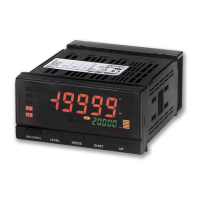
Short Body with Depth of Only 95 mm (from
Behind the Front Panel)
• A short body of only 95 mm (see note) contributes to the de-
velopment of slimmer and smaller control panels and instal-
lations.
Note: Depth of DeviceNet models is 97 mm.
Select a Comparative Output Pattern to Suit
the Discrimination or Control Application
• The output pattern for comparative outputs can be selected.
In addition to high/low comparison with set values, output
based on level changes is also possible. (Use the type of out-
put pattern appropriate for the application.)
Note: The HH, H, L, or LL outputs must be set in that order for the
zone outputs to output correctly.
(This is because the comparative set values and outputs for
standard and level outputs are in a 1-to-1 relationship, whereas
the meaning of zone outputs depends on the settings of all the
comparative set values.)
Lineup Includes DeviceNet Models Enabling
High-speed Data Communications with PLCs
without Special Programming
• DeviceNet compliance enables high-speed data transmis-
sion by allocating setting and monitoring parameters in the
I/O memory of the PLC. This capability greatly reduces labor
spent in developing communications programs.
UPSHIFTMODELEVEL
T-ZR
Zero
CMW
Max
B
L
Min
Hold
MAX/MIN
TG HH H
TLLL
Position mete
HH
H
P
L
LL
Measurement value
Input
Time
Peak-to-peak value
(b2−a2)
(b1
−
a1)
'b2
'a2
a1
b1
TIMING
input
Input
Time
ON
OFF
TIMING
input
ON
OFF
Sampling hold value
Measurement value
Peak-to-peak hold
measurement
Sampling
measurement
OFF
ON
Input
Time
Bottom hold value
Peak hold value
Peak/bottom hold
measurement
TIMING
input
Measurement
value
Peak value
Sampling at 15 times/second Sampling at 50 times/second
96
Timing of
internal
sampling
Time
100
0
Timing of
internal
sampling
Time
Depth: 95 mm (See note.)
27%
shorter
than earlier
models
(The depth is 100 mm when mounted to the terminal cover.)
ON
OFF
ON
OFF
ON
OFF
Standard Output
Zone Output
Comparative
set value HH
Comparative
set value H
Comparative
set value L
Comparative
set value LL
Measurement
value
Higher
Lower
Output HH
Output PASS
Output H
Output L
Output LL
Measurement
value
Higher
Lower
Measurement
value
Higher
Lower
Comparative
set value HH
Comparative
set value H
Comparative
set value L
Comparative
set value LL
Output HH
Output PASS
Output H
Output L
Output LL
Comparative
set value HH
Comparative
set value H
Comparative
set value L
Comparative
set value LL
Output HH
Output PASS
Output H
Output L
Output LL
Level Output
DeviceNet
Configurator
DeviceNet
Master
Ethernet
K3HB
Digital Indicators
P
H
Zero
P
Zero