Do you have a question about the Omron K3HB and is the answer not in the manual?
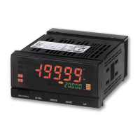
Measurement value display switches between red and green based on comparative outputs.
View present value against display range on a bar display for intuitive status grasp.
Synchronized detection and judgment using external signals for wide application possibilities.
Compact 95 mm depth contributes to slimmer and smaller control panels.
Choose output patterns for comparative outputs like high/low or level changes.
Sampling cycle at least three times faster than earlier models for improved response times.
DeviceNet compliance enables high-speed data transmission via PLC I/O memory.
Indicates Voltage/Current Signals with various input types.
Indicates Weight Measurements Using a Load Cell with various inputs.
Indicates Temperature Measurements, supporting Pt100 and thermocouples.
Measures and discriminates results at high speed with linear sensors.
Features easy judgment recognition, position meter, event input, and DeviceNet.
Legend for constructing model numbers by selecting base units and optional boards.
Details model number components: input sensor, output types, and supply voltage.
Lists optional accessories like special cables for event inputs and BCD output.
Details power supply, power consumption, current, input, and external power supply specs.
Describes timing input, startup compensation, hold, reset, and forced-zero inputs.
Specifies ratings for relay, transistor, linear outputs, and display method.
Lists key functions like scaling, averaging, and display color selection.
Specifies operating temperature, humidity, and applicable standards.
Details display range, sampling period, and response times for outputs.
Details immunity levels against noise and resistance to vibration/shock.
Details degree of protection ratings and applicable EMC standards.
Specifies input ranges and accuracy for DC voltage input types.
Specifies input ranges and accuracy for DC current input types.
Specifies input ranges and accuracy for AC voltage input types.
Specifies input ranges and accuracy for AC current input types.
Features color display, position meter, event input, DeviceNet, and short body.
Legend for constructing model numbers by selecting base units and optional boards.
Details model number components: input sensor, output types, and supply voltage.
Lists optional accessories like special cables for event inputs and BCD output.
Details power supply, power consumption, current, input, and external power supply specs.
Describes timing input, startup compensation, hold, reset, and forced-zero inputs.
Specifies ratings for relay, transistor, linear outputs, and display method.
Lists key functions like scaling, averaging, and display color selection.
Specifies operating temperature, humidity, and applicable standards.
Details display range, sampling period, and response times for outputs.
Details immunity levels against noise and resistance to vibration/shock.
Details degree of protection ratings and applicable EMC standards.
Specifies input ranges and accuracy for load cell mV input types.
Features color display, position meter, event input, DeviceNet, and short body.
Legend for constructing model numbers by selecting base units and optional boards.
Details model number components: input sensor, output types, and supply voltage.
Lists optional accessories like special cables for event inputs and BCD output.
Details power supply, power consumption, current, input, and external power supply specs.
Describes timing input, startup compensation, hold, reset, and forced-zero inputs.
Specifies ratings for relay, transistor, linear outputs, and display method.
Lists key functions like scaling, averaging, and display color selection.
Specifies operating temperature, humidity, and applicable standards.
Specifies display range and accuracy for thermocouple and Pt100 inputs.
Details sampling period and response times for comparative/linear outputs.
Details immunity levels against noise and resistance to vibration/shock.
Details degree of protection ratings and applicable EMC standards.
Shows input ranges, setting codes, and minimum units for temp sensors.
Features high-speed response, color display, position meter, DeviceNet, and short body.
Legend for constructing model numbers by selecting base units and optional boards.
Details model number components: input sensor, output types, and supply voltage.
Lists optional accessories like special cables for event inputs and BCD output.
Details power supply, power consumption, current, input, and external power supply specs.
Describes timing input, startup compensation, hold, reset, and forced-zero inputs.
Specifies ratings for relay, transistor, linear outputs, and display method.
Lists key functions like scaling, averaging, and display color selection.
Specifies operating temperature, humidity, and applicable standards.
Details display range, sampling period, and response times for outputs.
Details immunity levels against noise and resistance to vibration/shock.
Details degree of protection ratings and applicable EMC standards.
Specifies input ranges and accuracy for DC voltage/current inputs.
Describes output refresh periods for one or two inputs.
Explains calculation of comparative output response time.
Details ratings for contact and no-contact event inputs.
Specifies ratings for contact and transistor outputs.
Details allowable load impedance, resolution, and output error.
Specifies communication methods, synchronization, baud rate, and data length.
Details BCD input/output ratings and signal logic.
Details DeviceNet communication protocol and standards.
Describes Remote I/O and Message communications.
Explains how to allocate I/O data using the Configurator.
Details connection methods and required cabling.
Provides network length limits and max nodes/slaves.
Specifies power supply, voltage limits, and error checks.
Diagram showing internal components and data flow.
Details indicators for Max/Min, Level/Bank, PV, SV, and Comparative Outputs.
Explains MAX/MIN, LEVEL, MODE, SHIFT, and UP keys for operation.
Illustrates timing for single sampling and continuous BCD data output.
Wiring examples for connecting to controllers and display units.
Diagram of terminal layout and operating power supply options.
Shows wiring for sensor power supply, PASS output, and linear outputs.
Wiring diagrams for various output types and DeviceNet connections.
Notes on EN/IEC compliance and indoor use for connections.
Analog input connection diagrams for K3HB-X, -V, -H, and -S models.
Event input wiring for terminal block and connector models.
Details on BCD Output Cable and Special Cable for event inputs.
Describes input calculation, two-input circuits, and supported models.
Explains different hold modes for capturing measurement values.
Functions for converting input signals and smoothing display data.
Details comparison, temperature shift, and teaching functions.
Functions for setting present value to zero for calibration or tare.
Options for selecting display values and restricting digit changes.
Functions to compensate for signal fluctuations and limit display to zero.
Settings to reduce flickering and customize display color.
Selectable output patterns and logic reversal for comparative outputs.
Functions to prevent chattering and manage measurement stop time.
Outputs comparative results other than PASS/errors from the PASS terminal.
Provides physical dimensions and panel cutout dimensions.
Guidance on terminal wiring and applying unit stickers.
Instructions for panel mounting and ensuring watertight packing.
Optimal viewing angles for LCD and details on waterproof packing.
Warnings about electric shock, protective circuits, and proper operation.
Cautions on debris, gases, disassembly, measurement categories, and environment.
Details safe locations, temperature, humidity, installation, and wiring practices.
Methods to avoid interference from high-frequency devices and surges.
Guidance on wiring, filters, and shielding to reduce inductive noise.
Details OMRON's exclusive warranty and limitations of liability.
Guidance on determining product suitability for specific applications and environments.
| Input Type | Thermocouple, RTD, Voltage, Current |
|---|---|
| Control Output | Relay, Voltage, Current |
| Communication | RS-485 |
| Mounting | Panel |
| Humidity | 25% to 85% |
| Supply Voltage | 100-240 VAC, 24 VDC |