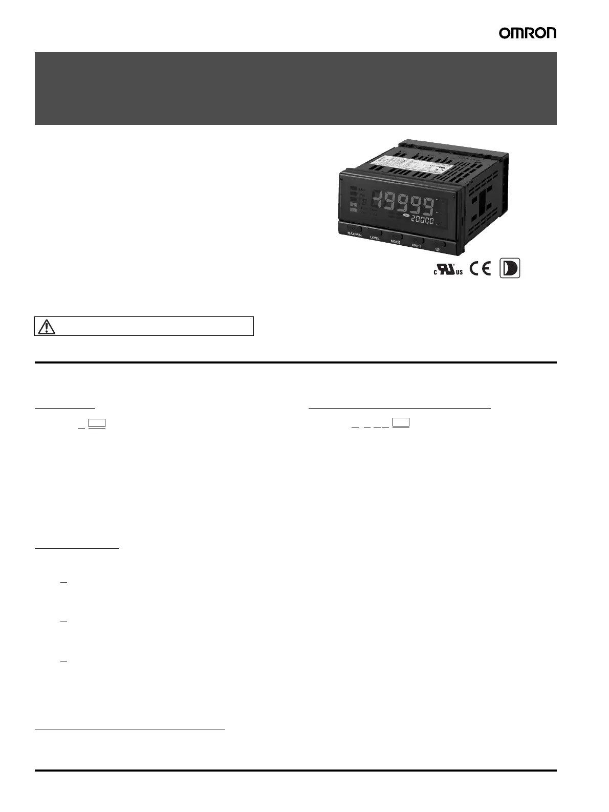
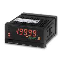
4 Process Indicator K3HB-X
Process Indicator
K3HB-X
A Process Indicator Ideal for Discriminating and
Displaying Measurements for Voltage/Current
Signals
• Easy recognition of judgement results using color display that can be
switched between red and green.
• Equipped with a position meter for monitoring operating status trends.
• External event input allows use in various measurement and discrimina-
tion applications.
• Series expanded to include DeviceNet models.
• Short body with depth of only 95 mm (from behind the front panel), or
97 mm for DeviceNet models.
• UL certification approval (Certification Mark License).
• CE Marking conformance by third party assessment body.
• Water-resistant enclosure conforms to NEMA 4X (equivalent to IP66).
• Capable of high-speed sampling at 50 times per second (20 ms)
• Easy-to-set two-point scaling allows conversion and display of any user-
set values.
Refer to Precautions on page 30.
Model Number Structure
■ Model Number Legend
Base Units and Optional Boards can be ordered individually or as sets.
Base Units
1. Input Sensor Codes
VD: DC voltage input
AD: DC current input
VA: AC voltage input
AA: AC current input
5. Supply Voltage
100-240 VAC: 100 to 240 VAC
24 VAC/VDC: 24 VAC/VDC
Base Units with Optional Boards
2. Sensor Power Supply/Output Type Codes
None: None
CPA: Relay output (PASS: SPDT) + Sensor power supply
(12 VDC +/−10%, 80 mA) (See note 1.)
L1A: Linear current output (DC0(4) − 20 mA) + Sensor power supply
(12 VDC +/−10%, 80 mA) (See note 2.)
L2A: Linear voltage output (DC0(1) − 5 V, 0 to 10 V) + Sensor power supply
(12 VDC +/−10%, 80 mA) (See note 2.)
A: Sensor power supply (12 VDC +/−10%, 80 mA)
FLK1A: Communications (RS-232C) + Sensor power supply
(12 VDC +/−10%, 80 mA) (See note 2.)
FLK3A: Communications (RS-485) + Sensor power supply
(12 VDC +/−10%, 80 mA) (See note 2.)
Optional Board
Sensor Power Supply/Output Boards
Relay/Transistor Output Boards
Event Input Boards
3. Relay/Transistor Output Type Codes
None: None
C1: Relay contact (H/L: SPDT each)
C2: Relay contact (HH/H/LL/L: SPST-NO each)
T1: Transistor (NPN open collector: HH/H/PASS/L/LL)
T2: Transistor (PNP open collector: HH/H/PASS/L/LL)
BCD: BCD output + transistor output (NPN open collector: HH/H/PASS/L/
LL)
DRT: DeviceNet (See note 2.)
4. Event input Type Codes
None: None
1: 5 points (M3 terminal blocks) NPN open collector
2: 8 points (10-pin MIL connector) NPN open collector
3: 5 points (M3 terminal blocks) PNP open collector
4: 8 points (10-pin MIL connector) PNP open collector
Note: 1. CPA can be combined with relay outputs only.
2. Only one of the following can be used by each Digital Indicator:
RS-232C/RS-485 communications, a linear output, or DeviceNet communications.
Accessories (Sold Separately)
K32-DICN: Special Cable (for event inputs, with 8-pin connector)
K32-BCD: Special BCD Output Cable
1
K3HB-X@
5
1234
K3HB-X@-@@@
5
2
K33-@
3
K34-@
4
K35-@