9. Appendix 1 Detailed Settings of the Tag Data Links
48
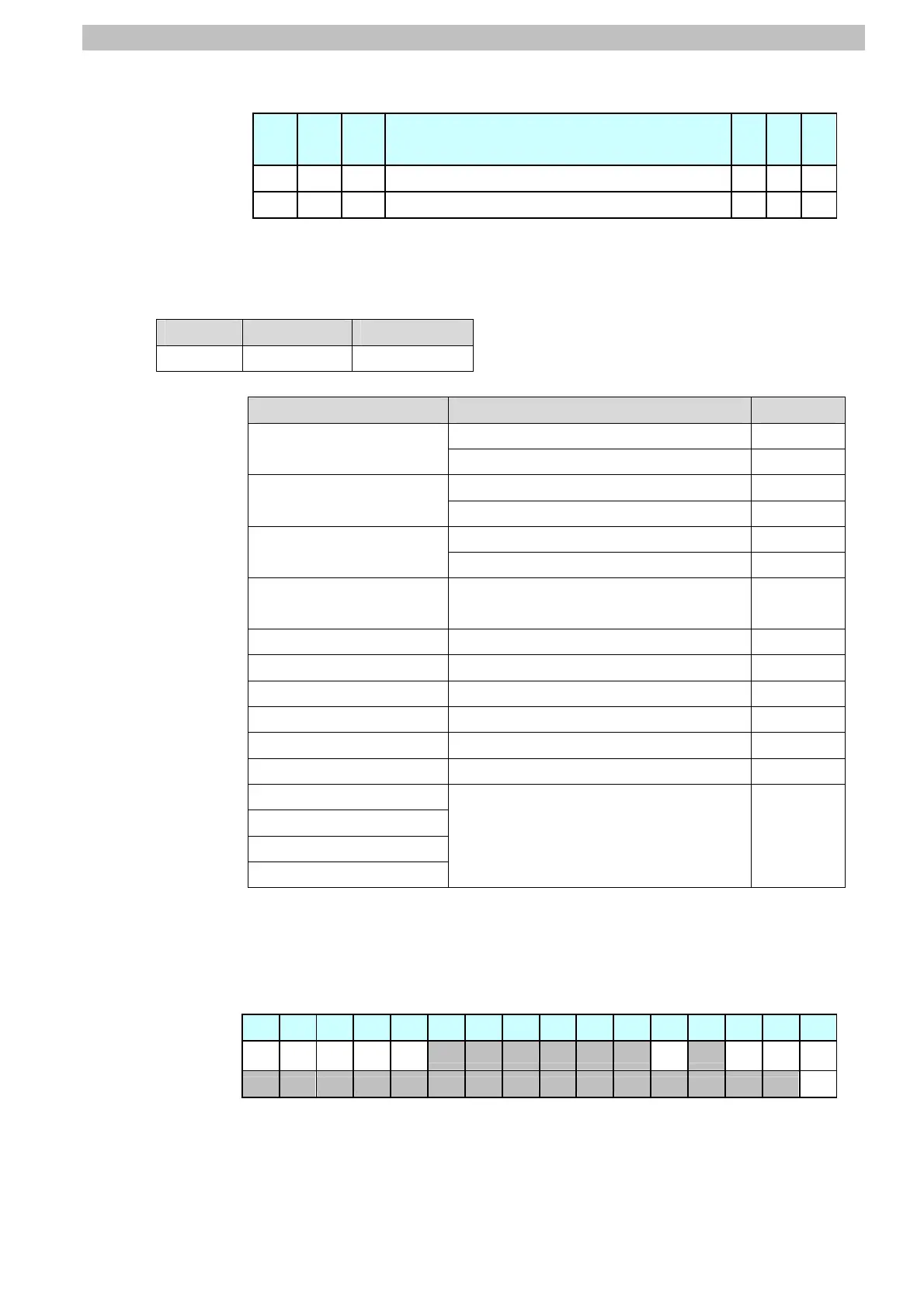
Allocation of EIPOutput.SensorHead2ControlReserve.W variable
Offset
(word)
15 14 13 … 2 1 0
+4 15 14 13 … 2 1 0
+5 31 30 29 … 18 17 16
Bits 31 to 0: EIPOutput.SensorHead2ControlReserve.W uses DWORD data
from offset + 2 words.
■Input area (Controller ← Displacement Sensor)
Variable Data type Data size
EIPInput S_EIPInput 56 bytes
Offset (word) Destination device data Name Data type
EIPInput.CommonStatusFlag.F
*4
BOOL[32]
+0 and +1
Control output 1
*1
(32 bits)
(Data type: U_EIPFlag)
EIPInput.CommonStatusFlag.W
*4
DWORD
EIPInput.SensorHead1StatusFlag.F
*5
BOOL[32]
+2 and +3
Control output 2
*2
(32 bits)
(Data type: U_EIPFlag)
EIPInput.SensorHead1StatusFlag.W
*5
DWORD
EIPInput.SensorHead2StatusReserve.F
*6
BOOL[32]
+4 and +5
Control output 3
*3
(32 bits)
(Data type: U_EIPFlag)
EIPInput.SensorHead2StatusReserve.W
*6
DWORD
+6 and +7
Command code
(CMD-CODE)
EIPInput.CommandCodeEcho DWORD
+8 and +9 Response code (RES-CODE) EIPInput.ResponseCode UDINT
+10 and +11 Response data (RES-DATA) EIPInput.ResponseData DINT
+12 and +13 Output data 0 (DATA0) EIPInput.MeasurementValueofTask1 DINT
+14 and+15 Output data 1 (DATA1) EIPInput.MeasurementValueofTask2 DINT
+16 and +17 Output data 2 (DATA2) EIPInput.MeasurementValueofTask3 DINT
+18 and +19 Output data 3 (DATA3) EIPInput.MeasurementValueofTask4 DINT
+20 and +21 Output data 4 (DATA4)
+22 and +23 Output data 5 (DATA5)
+24 and +25 Output data 6 (DATA6)
+26 and + 27 Output data 7 (DATA7)
EIPInput.MeasurementValueReserve DINT[4]
*1: Sensor head common status signal
*2: Sensor head 1 status signal
*3: Sensor head 2 status signal (reserved)
*4: Details on allocation of sensor head common status signal
Allocation of EIPInput.CommonStatusFlag.F variable
Offset (word) 15 14 13 12 11 10 9 8 7 6 5 4 3 2 1 0
+0
BANK1
_E
BANK1
_D
BANK1
_C
BANK1
_B
BANK1
_A
RUN READY
SYNC
FLG
FLG
+1
ERR
FLG: Control command completion bit: Turns ON when the displacement
sensor completes control command execution.

 Loading...


