10. Appendix 2 Setting the Tag Data Links Using the Software
6
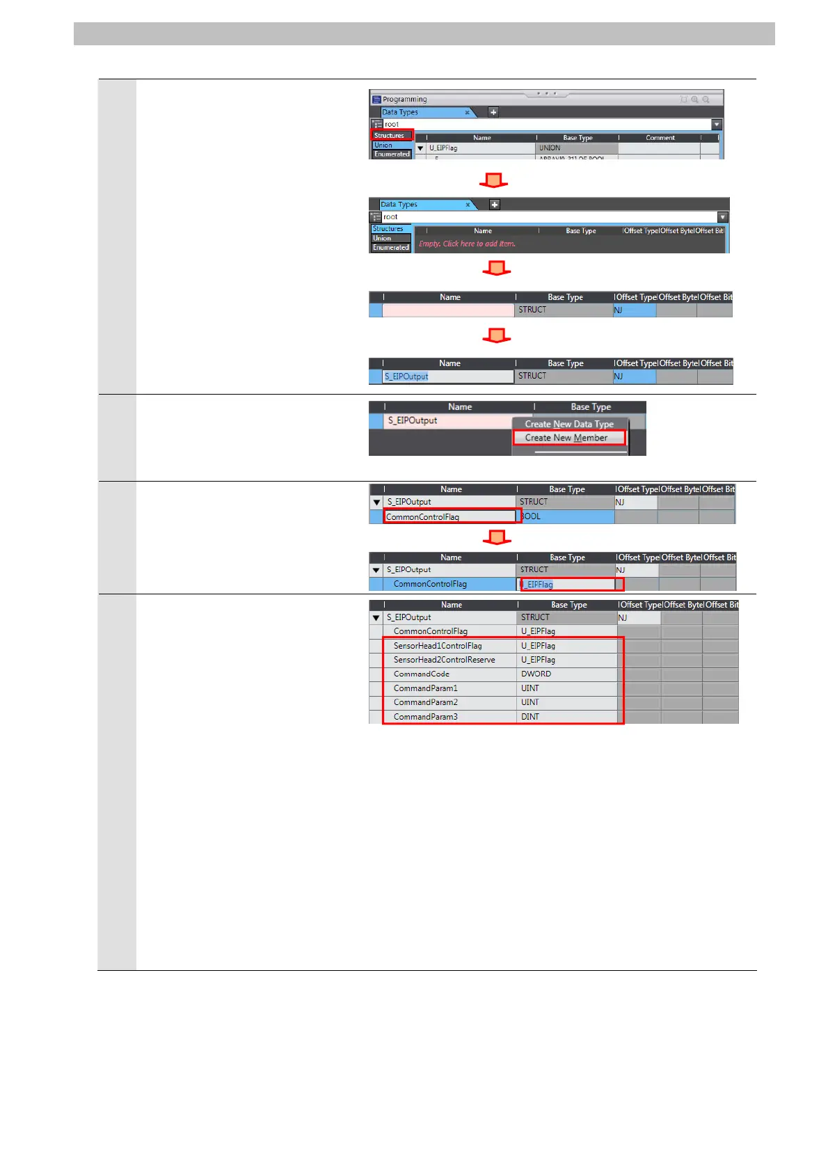
Click the Structures Tab in the
Edit Pane.
Display the Structures Tab on
the Data Types.
Click a Name Column to enter a
new data type.
Enter S_EIPOutput in the Name
Column.
7
After entering, right-click and
select Create New Member
from the menu.
8
Enter CommonControlFlag in
the Name Column.
Enter U_EIPFlag in the Base
Type Column.
9
In the same way as steps 7 and
8, enter the following data in the
new columns.
•Name:
SensorHead1ControlFlag
Data type: U_EIPFlag
•Name:
SensorHead2ControlRese
rve
Data type: U_EIPFlag
•Name: CommandCode
Data type: DWORD
•Name: CommandParam1
Data type: UINT
•Name: CommandParam2
Data type: UINT
•Name: CommandParam3
Data type: DINT
*Make sure that members are
displayed in order of the offsets
listed in Section 9.2.
60

 Loading...


