4-2 1:N Host Connection
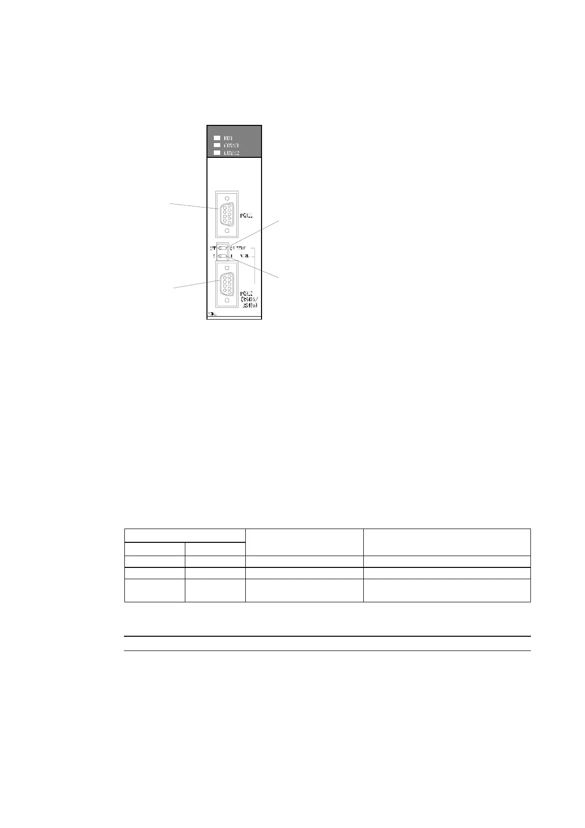
Setting the Front Panel Switches
• Using RS-422A
Port 1
RS-232C
Port 2
RS-422A
Terminating resistance switch (TERM)
Set to ON:
Terminating resistance used
(right position)
Two-wire/four-wire switch (WIRE)
For RS-422A:
Set to 4 for four-wire (right position).
Connecting to CS-series Serial Communications Units
CS-series Rack-mounted Type:
CS1W-SCU21 (Both ports 1 and 2 are RS-232C ports.)
CPU Unit DM Area Settings
• Using RS-232C
Write the settings directly from the Programming Device or Support Software (Programming
Console or CX-Programmer) to the DM Area (Parameter Area) in the CPU Unit. After writing
the settings, enable the settings by turning ON the power again, restarting the Unit, restarting
the communications port, or executing the CHANGE SERIAL PORT SETUP (STUP) instruc-
tion.
The following table shows the allocated DM Area words and settings.
m = 30000 + 100 × unit number
Allocated DM Area words
Port 1 Port 2
Write value Settings
DM m DM m + 10 8200 1:N NT Link Mode
DM m + 1 DM m + 11 0000 to 0009 (See note 1.) Baud rate (normal)
DM m + 6 DM m + 16
000@ @: Largest unit number (1 to 7) of the
connected PTs. (See note 2.)
Note 1. Set the baud rate to a numeric value between 0000 to 0009 Hex. (The setting is the same for
any value between 0000 and 0009 Hex.)
2. When using a 1:N connection, set the value for @ to 1 or higher.
Reference When setting a 1:N NT Link in the CX-Programmer, set the baud rate to 38,400 bps.
4-13
 Loading...


